I actually only joined this forum to see how John "Blogwitch" ex "Bogstandard" was getting on; I see he's not logged on since last October.
There seems to be a few folk who have missed the basic principal behind the way John designed the tool/gauge.
The most important aspect is that the arbor is perfectly parallel to the two separate feet at the ends.
That being the case, if you stand the gauge on a flat surface, the arbor is exactly perpendicular to that surface.
The idea is that you fit the two gauges, sufficiently high in their respective holes, that the plungers can fully retract when when the gauge is stood on its feet.
Next job is to set them at the same height, lock the allen screws, and zero the clocks.
That's all you need to do in order to calibrate the gauge.
Essentially, if the gauge is fitted to the arbor and the table is perpendicular, the two feet will be equidistant from the table; the clocks are only there to indicate the difference between the two ends.
You have previously zero'd the clocks with the feet on a flat surface, so they now show the two distances, one at each end.
This indicates which way, if any, that the table is out of square with the arbor/spindle.
The main difference between John's design and mine is that his used a parallel arbor, whereas I've used an MT2 taper, to suit both my milling machines; a Centec 2B and a Dore Westbury.
John went to great lengths to ensure perpendicularity; as did I, though I fitted the arbor into the spindle of my Myford (with a drawbar) and took the feintest skim off the two feet.
My tool/gauge in its box;
 Mill Tramming Tool/Gauge
 by
Bill Williams, on Flickr
Sitting on a flat surface to zero the clocks. Any flat surface will do; these appear to be slightly different, but that's parallax error from the central camera
 Mill Tramming Tool/Gauge
 by
Bill Williams, on Flickr
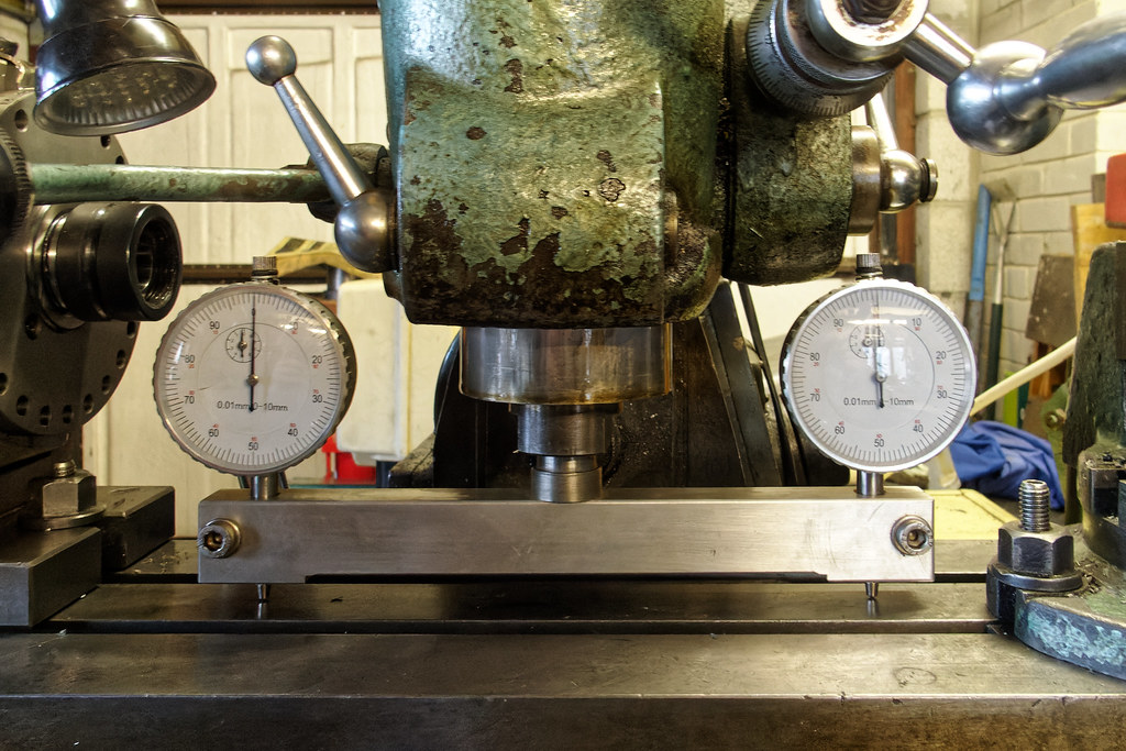
Now set up in the spindle and just touching the table with the two clock plungers.
As you can see, the left clock impacted first, by about 18 thou over 8"
 Mill Tramming Tool/Gauge
 by
Bill Williams, on Flickr
Centec head now trued up; again slight parallax error is a bit misleading
 Mill Tramming Tool/Gauge
 by
Bill Williams, on Flickr
Finally, if you don't want to wind the table all the way up, a couple of precision ground blocks will assist.
 Mill Tramming Tool/Gauge
 by
Bill Williams, on Flickr
If you want to spin the whole arrangement around to check the nod, either use a long enough precision parallel, or a brand new car brake disk.
The latter is likely precision ground out of the factory, and has the advantage that the clock plungers don't drop into the Tee slots as you rotate the spindle.
Also, once everything is set true, I then slackened off the arbor in the spindle, rotated the spindle 60°, nipped up the drawbar again and re-measured.
I did this for one full rotation of the Centec spindle, as that would show if there was anything bent, or bruised inside the taper, thus throwing the arbor out from the axis of rotation.
I'm hoping this clears up a few points in the absence of John being around to comment himself.
I did discuss my method of construction and use with him when I called in and bought some kit as part of his great workshop clearance.
All the best
Bill


