It might be interesting to look at the indicator (or P-V) diagram with a little
more attention to detail,
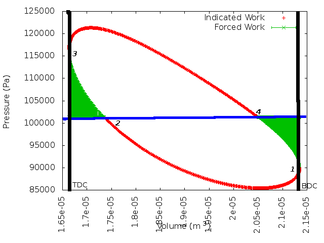
I've drawn in vertical black lines to show that the point of maximum volume
is when the power piston is at Bottom Dead Center (BCD) and at a minimum at
Top Dead Center.
The Blue line represents "Buffer Pressure" which is in this case atmospheric
pressure. Senft points out that a practical engine running will through (however
small) leakage past the piston quickly equalize to have an average internal
pressure equal to the Buffer Pressure.
I've added numbers to the "oval" indicator line to point out key details in the cycle.
Imagine that the engine has come to speed and the average internal pressure
is equal to atmospheric -the blue line-.
Starting at "1", Bottom Dead Center, the piston starts moving inward. since the
engine pressure is less than atmospheric, the piston is being "pushed" in by
atmospheric pressure. This is consistent with the momentum of the flywheel.
At "2", the situation changes. The engine pressure is now higher than atmospheric
but the piston is still moving inward, so in the portion of the cycle between
"2" and "3", the piston opposes the flyweel. Between "2" and "3", the
flywheel is putting compression work back into the engine. Senft calls this
Forced Work. In terms of accounting for work at the shaft, The portion between
"1" and "2" was adding work to the flywheel, while betwen "2" and "3" work is
being taken from the flywheel.
At "3", the piston reverses and starts its trip outward. Since internal pressure
is higher than atmospheric, the piston is adding work to the flywheel. Finally,
between "4" and "1" the flywheel has to supply work until the piston reverses
at "1".
The concept of Forced Work is important here because if an engine was designed
with only attention to Indicated Work, the end result might be an engine in
which Forced Work was higher than Indicated Work. That would result in a
negative Shaft Work, and an engine that would not run.
Regards,
--Tim


