More progress...in this installment I attach the cylinder head.
For this I got to use my spankin' new rotary table that I bought as a 50th birthday present for myself. I thought I may as well celebrate going over the hill! Besides, my wife got to claim she got it for me. I'm good with that

I was originally planning to just measure out the screws, but this was more fun, and fortunate for me, didn't really require much accuracy. Still, I wanted to try to be as accurate as I could for the practice.
I started by centering the RT using a dead center (it has a MT2 in the middle). I used a 5/8" collet to center on the point (no photos of this), and it worked pretty good. I had to tweak it with a DI moving about 10 thousands at most to finish it off. Someday I need to make a tool specifically for this, and it'll give me an excuse to make a taper on centers in the lathe which is something I've never done.
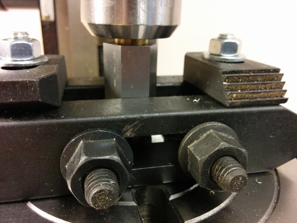
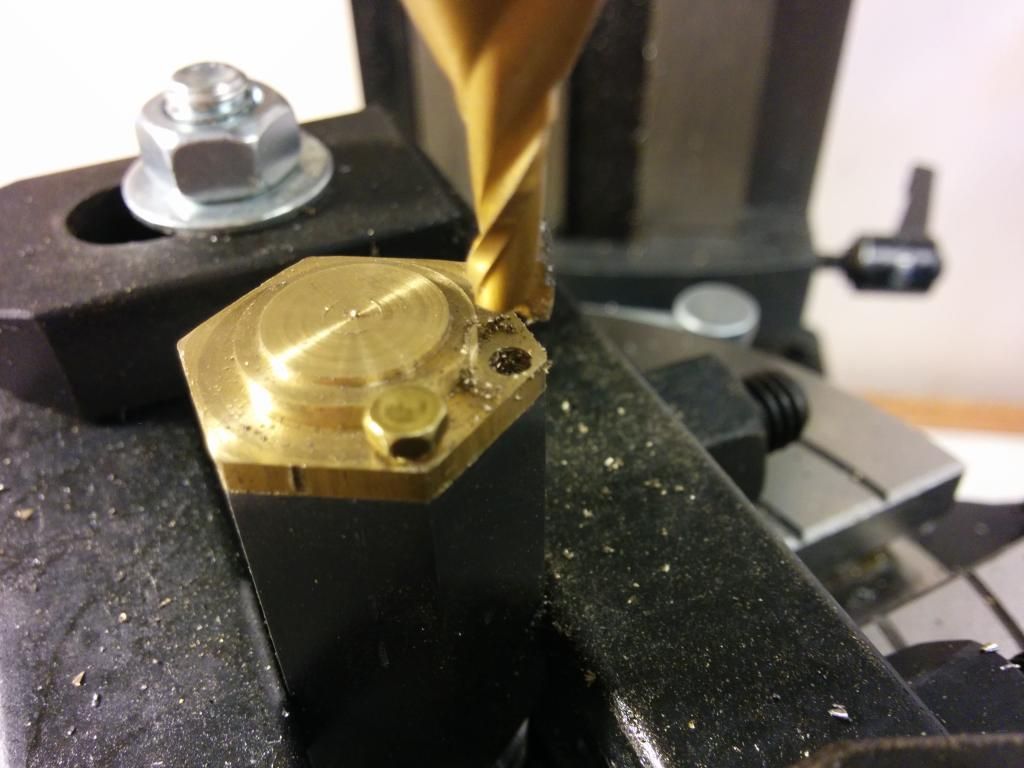
In this photo I'm centering the cylinder on the RT. My vise is too high for my mill, so I had to get creative bolting it down. I maybe could have made the setup rigid enough for heavy milling (so to speak -- I have a X2-style mill), but I'm only drilling/taping holes so I wasn't too worried about that. I happen to have a "spare" (i.e. too small) piston I made earlier in the project, and that is the bit of brass you see centering the mill onto the cylinder.
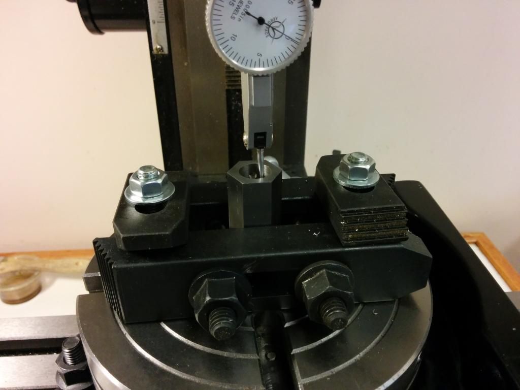
Here I used a DI to finish centering. It was only 5 thou or so off.
I cranked it over 5/16 of an inch for the screws. I had violated a rule I always use in woodworking -- don't work on a project until you have all the hardware. These 3-48 "bolts" are pretty cool, but a little bigger than I expected. I also had some 2-56, but they weren't as well defined. I ended up dialing it out another 35 thousands to make room, wishing I had turned the cylinder head in a little more than I did

.
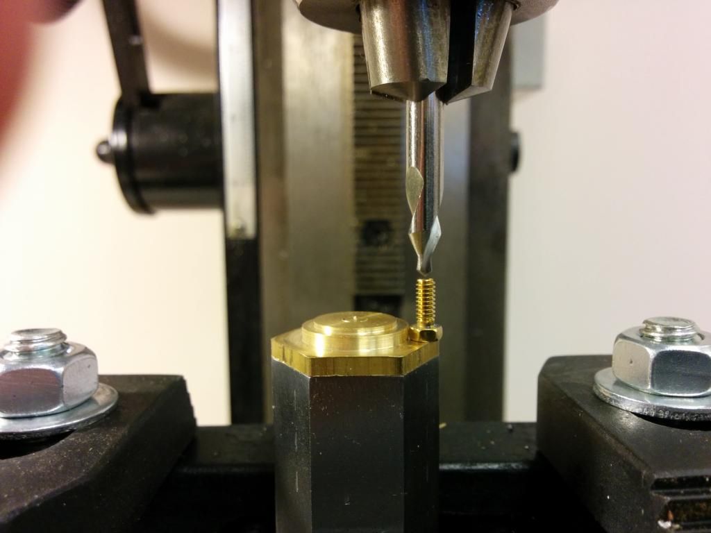
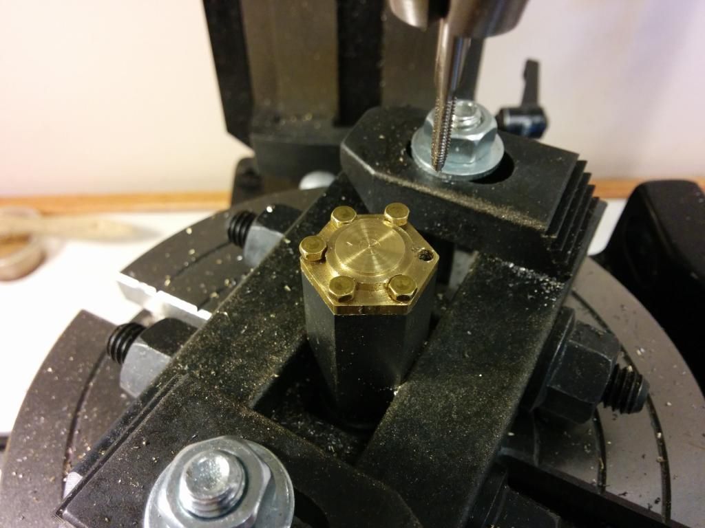
I used a couple drops of superglue to attach the head, then I drilled and tapped. It came out a little too tight...the hex head rubbed the cylinder head. Doh!
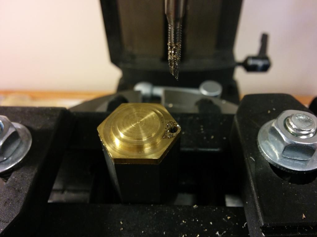
Here I drilled for the second screw after moving it out another 5 thousandths. It still didn't quite fit -- note the first bolt isn't seated all the way. It was better, but still rubbed. The bolts were getting way too close to the edge, so I decided to make artificial clearance using a 3/16" 2-flute end mill. That was the smallest end mill I had, and it actually was sized quite well. Lucky me.
I went all the way around, drilling, tapping, making clearance with the end mill, and installing the bolts as far as I could. I thought I should install the bolts because I didn't know if the superglue would hold it for the full operation.
The RT was working well -- 15 cranks for 60 degrees. Easy enough. I think measuring would have worked fine, too, though. I would have done the two across the center first, since the cylinder started on center. Then I'd do the two toward the mill column, and then shift Y and do the two away from the column. At least that was my plan before procuring the RT.
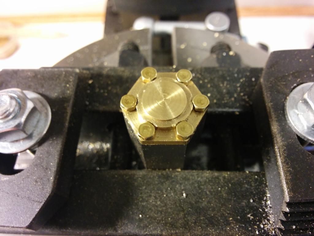
And here they are, pretty much done. I used some needle nose pliers to tighten them down further after I took the pic. I haven't actually separated the head from the cylinder. I suppose I should, and I should make the cylinder head holes into clearance holes, but for now I'm just leaving it as-is.
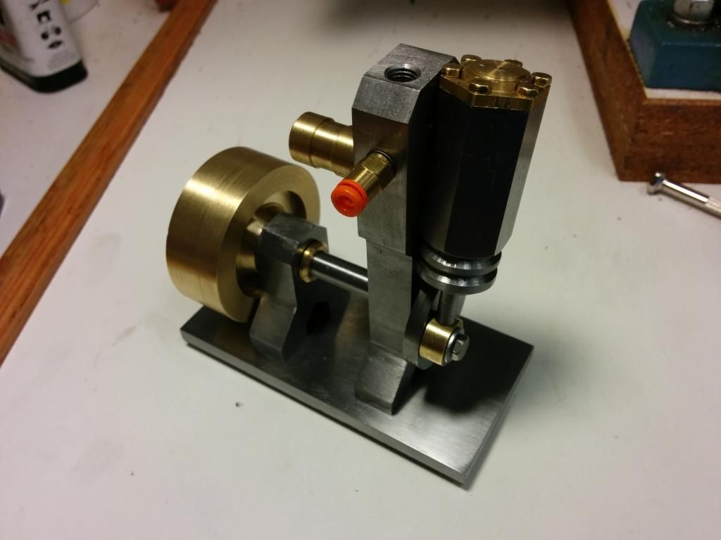
Here's the engine *almost* ready to run. I like the "engine-y" quality the bolts give it. The squeaker is still missing (the threads on the top).
Time to run this thing, don't you think?
Todd


