The crank was built up of 303 stainless steel and held together with loctite
retaining compound.
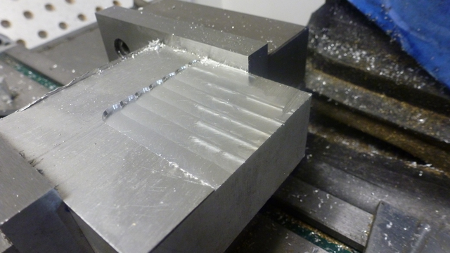
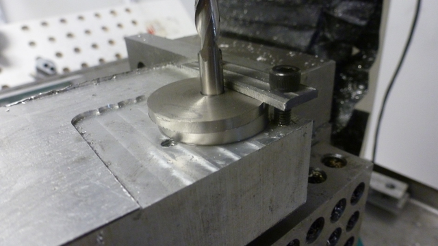
The first photo shows the beginning of a fixture for building the crank. An
aluminum block was clamped in the CNC mill and faced off to be square with the
machine.
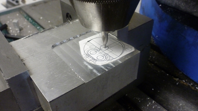
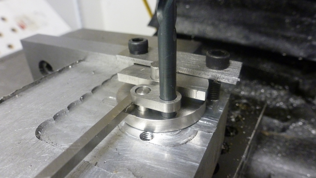
A paper cutout helped me to locate the position where I would drill for the
crank shaft.
A crank disk had already been turned with a hub and a reamed shaft hole (sorry
about the missing lathe pictures). The fixture was drilled and reamed for the
shaft, and the hole was enlarged near the top to clear the hub.
A large chamfer was made to accommodate the radius between the hub and the
crank disk.
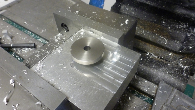
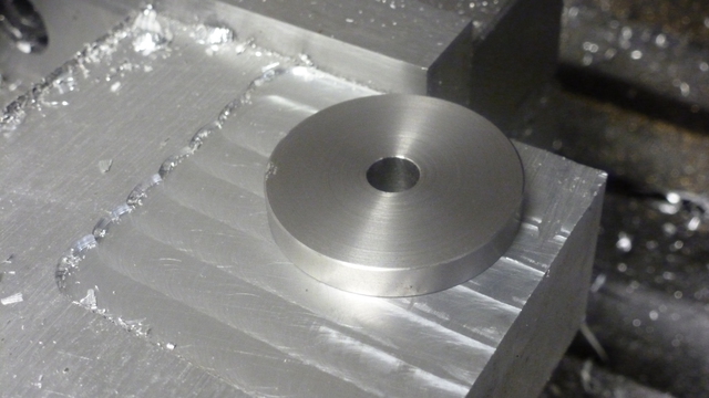
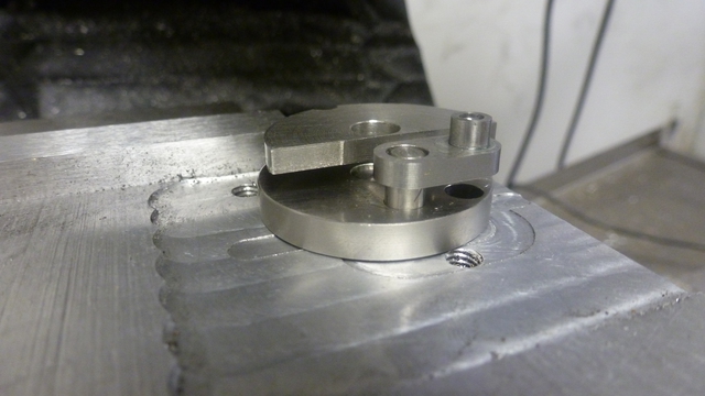
Here's the disk in place. You can see how the back of the disk sat nicely
on the fixture block.
A second disk drilled and reamed slightly off-center was placed on top of the
first and was aligned with a .25 mill shank. The fixture had been drilled
and tapped for clamping screws, and a strap clamp held the disks in place.
With the parts thus aligned and clamped, two crank pin holes were drilled and
reamed through both disks. The holes extended well into the fixture block to
be used for later alignment references.
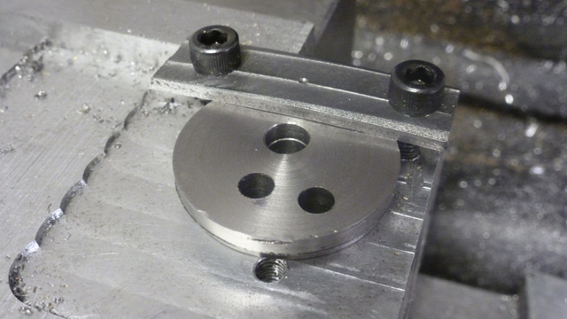
With the bottom disk removed, the previously reamed holes provided for
alignment of the upper disk with drill and mill shanks. The disk was clamped.
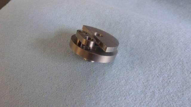
The disk was milled to define a small crank web between the crank pins. Note
the thin bridging piece left to keep the larger part with the center hole
intact. Keeping the larger piece attached facilitated fixture clamping and alignment.
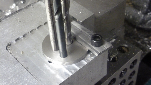
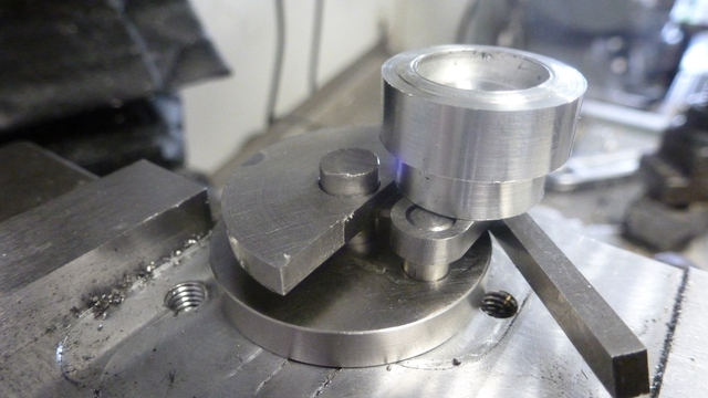
The parts were re-clamped, this time with the short piston crank pin loctited
in place. The drive shaft was temporarily used in the center hole for alignment,
along with a drill bit in the yet unused crank pin spot. Also, a 1/8 inch lathe
bit was used to establish the proper spacing between the disks.
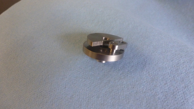
These photos shows the progress after the loctite cured on the first crank pin.
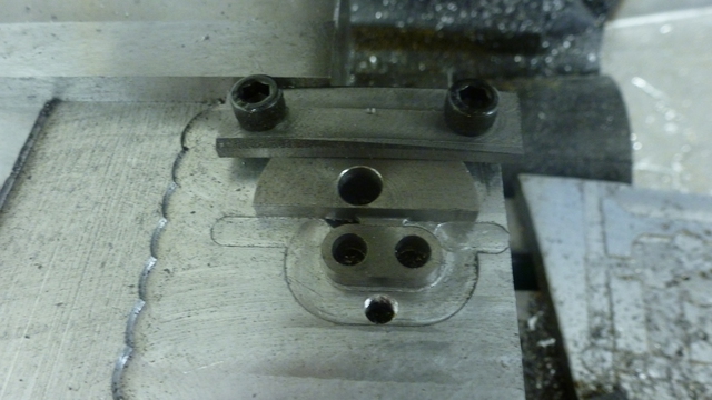
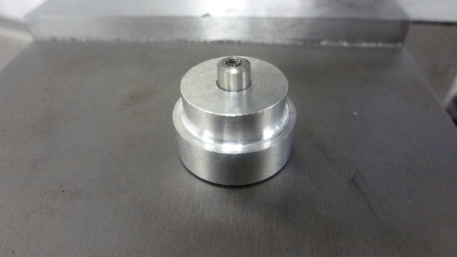
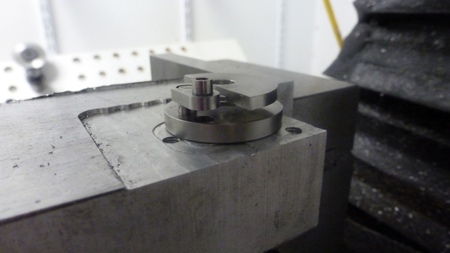
Shown in this photo is a fixture to help hold the displacer crank pin in
alignment. The crank pin is seen protruding out of the aluminum alignment fixture.
Here's the assembly with the displacer crank pin being loctited in. The aluminum
alignment fixture obscures the pin itself. Note the crank shaft is still inserted
to ensure alignment of the two disks during loctite cure.
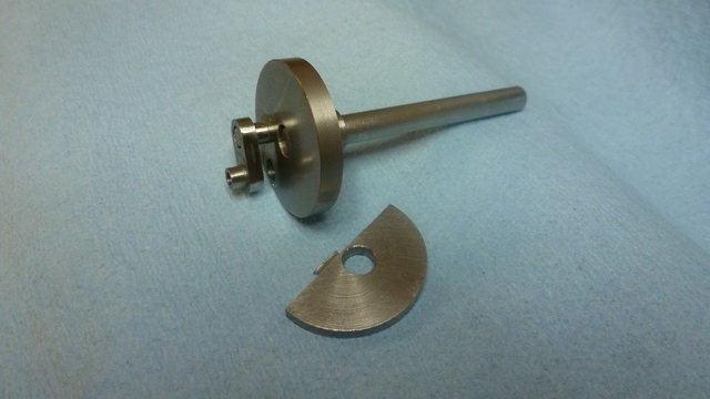
After the loctite had cured, the main shaft was loctited in its proper position
in the lower disk.
Finally, the extraneous fixturing part was sawed away with a jeweler's saw
to leave just the small web between the crank pins.
A note about the shaft and crank pins. They are made from 303 stainless
steel "Miniature Drive Shaft" material purchased in 3 inch lengths from
McMaster-Carr. The diameter and straightness tolerances are excellent.
--Tim


