Dave, I'm thoroughly enjoying this machine - I have a hunch I'm going to use it quite a bit!
I've played around a bit more with the TCG - just trying to get its "feel", which is completely different to that of a lathe or mill. It's important to keep in mind that this machine is intended to remove very small amounts of material at a time, but it's controls are all made to suit that. Making adjustments down to 0.01mm is very easy, and with a bit of care, it's easy to adjust things down to roughly 0.0025mm - though I have difficulty measuring this as all my measuring instruments go down to just 0.01mm...
One problem I have is that the selection of C5 collets that came with the machine are missing some sizes that I'll often use, and unfortunately some of the ones there at some point picked up quite a bit of rust, so I'm not sure how accurate those will be any more...
Joe kindly offered to make up a shared package for some stuff he'll be getting from LMS or ArcEuro to split shipping costs to Namibia, but after totaling the collet prices and compensating for international currency exchange rates, my Home Ministry of Finance (HMoF) determined that, even with the potential saving on shipping, sufficient funds are not available in the current financial budget for this capital expense

So I decided I'll do what I always do if funds are short - make a plan. Just over a year-and-a-half ago, I managed to smuggle a set of
"closer tolerance" ER25 collets past the HMoF, and I'm quite happy with those. Not as good as the stuff the guys States-side get, but a lot better than the even cheaper ones I already had. So, the plan for now consists of making a 5C to ER25 collet adapter for use on the TCG.
A bit of research on the Interwebs turned up the dimensions for the 5C collets - though I must say there are a lot of contradicting sizes and dimensions. So I "averaged" those to get an approximation. The ER25 side was less of a challenge; I've made ER25 chucks for both my lathe and mill, and both seem to work OK, so I just used the same dimensions. With all the information at hand, I took the extraordinary step of drawing the adapter up in CAD - converting all the Imperial sizes on the 5C side to Metric:
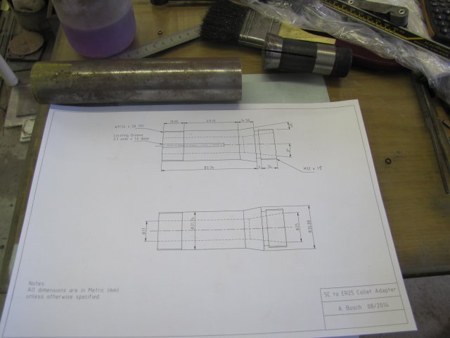
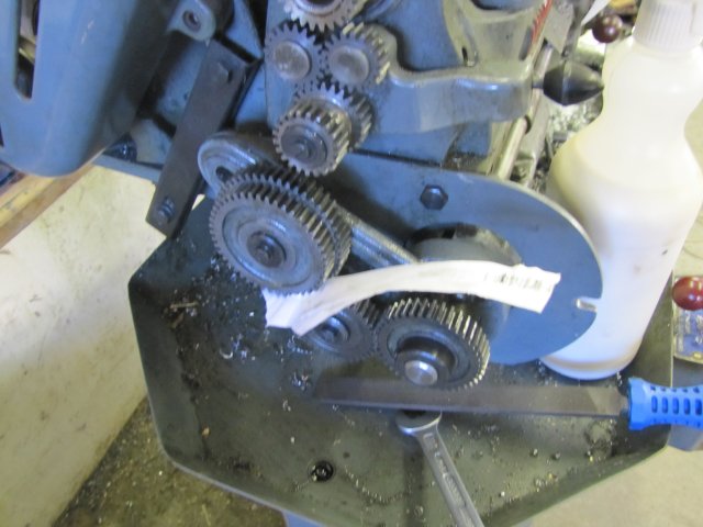
I already had a bit of stock to make the adapter from - visible in the photo above - a section of 40mm diameter EN8 steel. Not ideal - this steel is quite difficult to machine to a good finish, but that's what I have, so it's what I'll use. It was shortened a bit on the bandsaw to minimise wastage, and clocked up in the 4-jaw chuck:
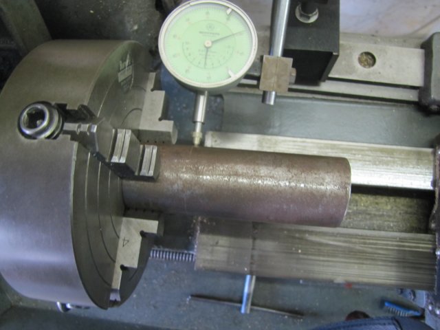
A bit of green Scotch-Brite worked a treat to clean off the surface rust on the circumference at the outer end and smooth it over , then I used the fixed steady to stabilize the end and faced it off:
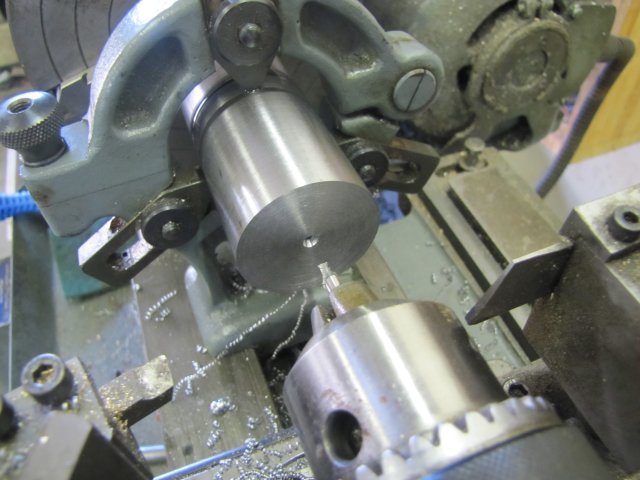
This is a fairly long workpiece, so I deemed it necessary to add the steady as additional support. After the above photo, I also center-drilled the end of the workpiece (this might be needed later).
Then I reversed the workpiece - leaving it sticking out further from the chuck than before, and clocked it up again. The brightened bit at the end from the last operation on the section where the steady ran made it easy to do it dead-nuts - with barely a flicker showing on the dial indicator. The rest of the rust on the workpiece was removed with Scotch-Brite, the fixed steady installed again, and the other end center drilled:
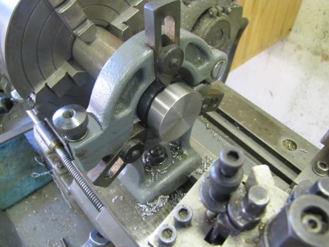
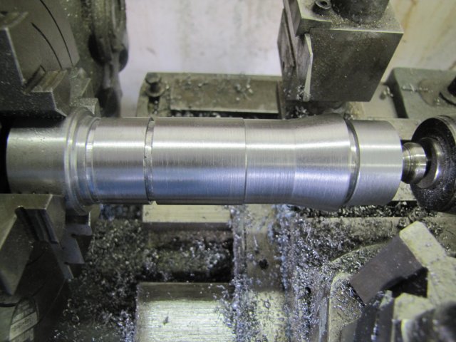
With that done, I could remove the steady and bring up tailstock support with the revolving center. The workpiece was roughly turned down its entire length to the dimension of the C5 head section(36.9mm), then the end turned down to 32mm for 18mm long, and a 4mm wide x 3mm deep thread run-out groove machined in with the rear parting tool:
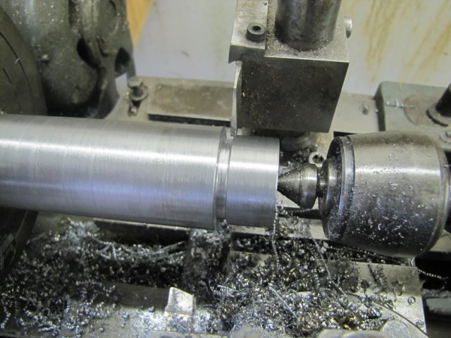
A section behind where the 5C taper would be was turned down to 31mm - this is not on the plans, but all the 5C collets I have, have the narrower section behind the taper, and would make turning the taper a bit easier. There's a section next to the threads that forms a register and must be accurate. Here I've turned down most of the workpiece to the register size:
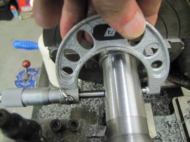
Rats... that section should have been 31.74mm - I took it a bit far and ended up at about 31.735mm:
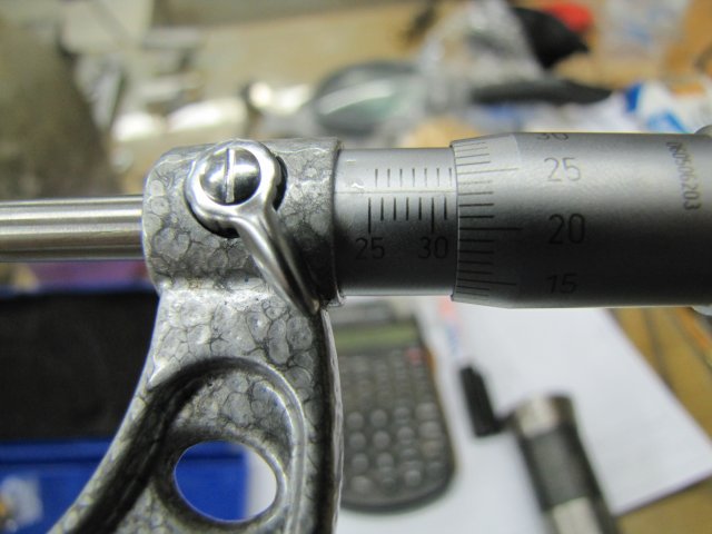
I hope that will be OK - only time will tell.
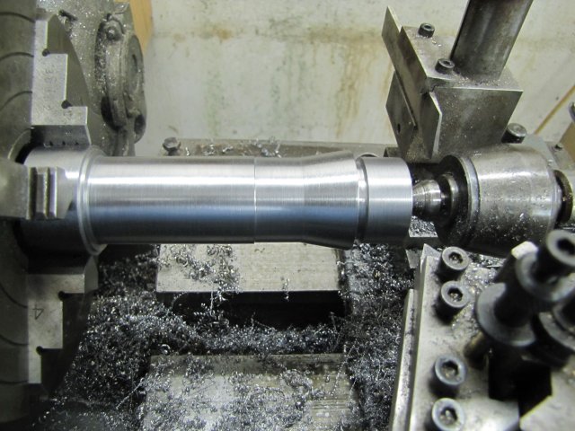
I turned the taper on the nose by setting the Myford's top slide to 10
o - I've found it's markings to be very accurate. Just an overview of progress thus far - that's where my shop session ended for Saturday:
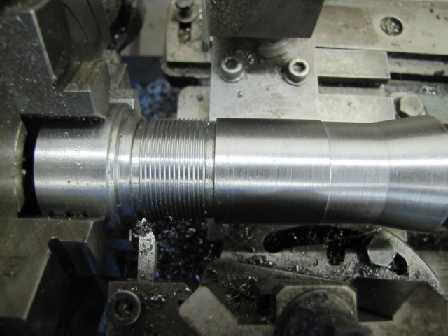
Today's shop session saw one of my favourite lathe operations - single point threading. For the 5C side of the adapter, I added two run-out grooves - the one closest to the chuck is also where the adapter will be parted off later:
Both the threads needed are 60
o form - the 5C end at an outer diameter of 31.54mm x 20 TPI, and the ER side 32mm x 1.5mm. To thread up to the 5C taper nose on the ER side, I needed to grind up a tool that would give adequate clearance. Easy-Peasy from a bit of 4.7mm HSS - which I then carefully honed till it was sharp enough to cleanly cut paper:
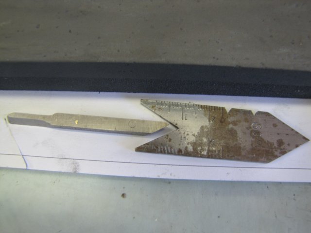
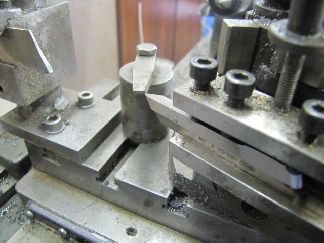
One of the rules of thumb for good thread-cutting (or turning in general for that matter), is that the toolbit should extend as little as possible from the toolpost - of course this depends on the thickness of the toolbit and other factors. In this case, I needed to have the toolbit extend quite a way out of the toolpost - simply for the top slide and toolpost to clear the tailstock on the ER side of the workpiece, as well as to clear the 5C "nose" while turning the threads on the 5C side of the workpiece. And the toolbit I made up is quite thin, so I added another HSS tool blank below it to give additional support - visible here while I was setting the correct height:
Normally one would use the gauge (sometimes called fishtail) shown in the photo just above the last to set the tool square to the workpiece, but this is a bit fiddly sometimes, and as I'm a lazy rotter, it's easier to make sure the toolbit's tip is ground correctly relative to the length of the toolbit, and then it's a simple matter of using a square to set the tool:
On to setting the lathe's leadscrew gearing for 1.5mm pitch. I paused and snapped a shot showing how I use a bit of paper to set the gear spacing on the banjo - boring, but the photo's there:
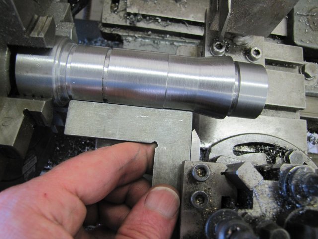
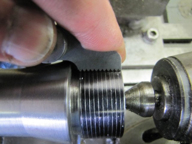
I've cut a handful or so of threads - there's one step I never skip, and that's to double-check the pitch after a very thin pass - here I'm checking the 32x1.5mm thread:
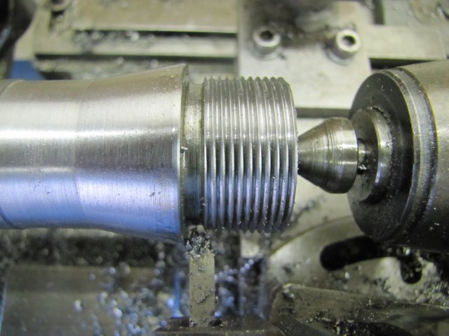
From the above operation, I also took the dial reading for the cross-slide - (86 thou), but I'd already used a thou for the pass, so 85 thou. A quick calculation gave the infeed needed for full depth of cut at 1.299mm - make that 1.3mm - and that is 51 thou, so final depth of cut would be at 137 (well, 37 as I'll pass zero on the handwheel). After a bunch of passes (lots of cutting fluid) - with decreasing depths of cut toward the end, the magic of the thread appearing happened. The last pass took just the minutest bit of swarf off visible on the toolbit:
Metric tread on an imperial lathe - so I had to keep the leadscrew engaged... I found a nice cheat way to reverse things though; I always screw-cut in back gear, and on the Myford it's possible to disengage back gear which leaves the chuck free from the motor drive, but the spindle remains engaged to the leadscrew geartrain. So it's easy to just turn the chuck by hand to reverse the lot. My lathe's motor doesn't like to be switched on and off all the time, and with the clutch, I leave it running forward pretty much all of the time while machining.
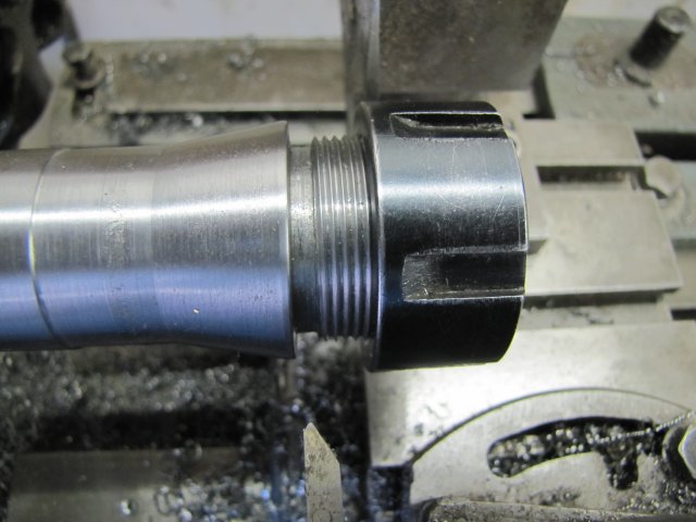
Couldn't resist a test

:
The gearing for the 20TPI thread was much simpler than for the 1.5mm pitch:
I could use the thread indicator and disengage and re-engage the leadscrew for the 20 TPI thread. Made it double-quick to do
:
Out with the fixed steady again - the section behind the 5C taper was ideal for this - and some deep-hole drilling commenced:
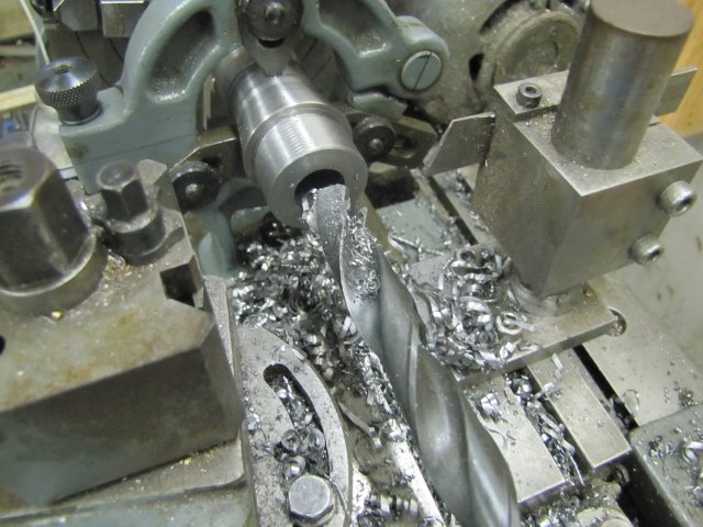
So close, yet so far; I wanted to finish this workpiece this weekend, but had to stop. There's some more drilling needed, and the 8
o ER taper bored before parting off...
Kind regards, Arnold


