A finger-treadle engine in the form of a spinning wheel.
My daughter spins wool and some time ago I thought it would be neat to make a model of one.
I haven't had much time in the shop but have done some drawings and a little experimentation in the time I do get.
It's a 1/5 scale model of a double-drive Castle style spinning wheel.
It won't spin fiber but I'd like it to be functional enough to spin two threads together to make 'yarn'.
Many of you know I started this some time ago. But I ran into a number of issues. The original was a model of a single-drive Saxony (or Cinderella) spinning wheel. But to get fibers (or threads) to spin requires a difference in speed between the bobbin and the flyer. With a single-drive this is accomplished by braking the bobbin with a tension-able band (a Scotch brake I think it's called). I realized this would be unlikely to accomplish on such a small scale. A double-drive system makes this more automatic.
I have a number of other requirements. For one, I didn't want it to look too 'machiney' (have at it Marv

). For instance, to mate two bars together you might drill and tap through both and bolt them. But I didn't want the hole to be seen on the other side. I would like to see a bolt on both sides. Since the hole depth is on the order of 1/4" I had to think of something else. You'll see this shortly.
I'd like to really bling this up but I expect I'll save that for later. By which time I may be so disgusted with my work that I'll move on to something else before I 'finish' it.
I've finished the drawings and started some experimenting. I'm not too happy with the design of a couple of aspects (the bed and more importantly the stand that holds the maiden) but it's a first go.
A real challenge (besides the scale) will be the flywheel. 3.6" diameter. (It may not fit my lathe!). In the early thread I was needled into considering a spoked wheel (some of you know who did the needling...his name starts with 'M', ends with 'v', and has the letters 'a' and 'r' somewhere in-between). So the current design is a brass ring with aluminum spokes and a split aluminum hub screwed together to keep everything in place. No idea if that will work.
So here's some pics. Sorry for the quality. I hope to get better at this too.
Here's a pic of the prototype:
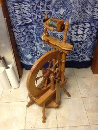
Don't know why it's sideways. The original picture was but I rotated it in PB and it shows rotated correctly in PB. But hey...it's wood and we don't want to look at it too long.
Here's a bobbin:
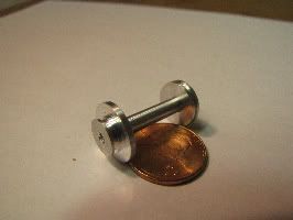
It came out pretty well but I doubt it will work. I need to chamfer the grooves so the band won't slip off.
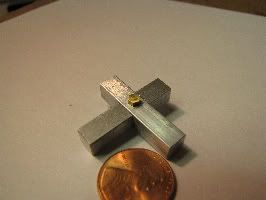
Here's what I meant about pinning two bars together. What I did was take 1/8" hex rod, made an 0-80 bolt and a 'pin'.
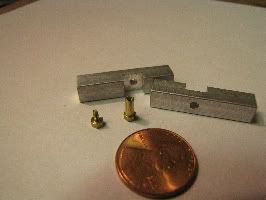
Here's the bolt in the pin:
Here's two bars pinned together. The other side looks the same.
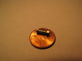
This next pic shows part of the flyer assembly. Fairly small. It's the 4th attempt and still I either got the central hole off or the sides milled at different distances. It's pretty rough. I used a steel button to try and round the edges as well as rounding around the central hole. Not a good job and I'll try again later.
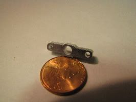
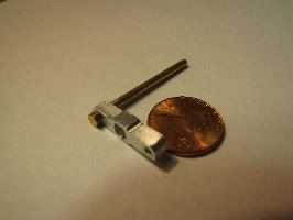
This pic shows one of the 'legs' of the flyer. That will be a challenge too. You have to have a way to move the fiber (thread) along the leg to fill the bobbin. On wood systems this is done with open eye-lets. I'm hoping spaced holes with a little slot to the side will do the same.
I have no idea when I can continue to work on this. It may even die a quiet death as my attention is easily distracted.


