Author Topic: Worm Gear Substitute  (Read 2930 times)

Offline cfellows

  • Rest In Peace
  • Full Member
  • *
  • Posts: 1700
Worm Gear Substitute
« on: April 05, 2014, 03:42:10 AM »
Here's something I made that might be of use to others.  In the past, I have made worm gear substitutes by simply cutting a spur gear with the teeth at an angle matching the angle of the teeth on the worm.  These work fine with no backlash in cases where the load is light.  The only real downside is that the worm teeth contact the gear teeth over a very small area instead of the entire gear width.

Over the past couple of days I have been thinking about a gear driven helical gear cutter and one of my design requirements is a worm gear assembly with a 10:1 ratio.  Since a worm gear with only 10 teeth is probably not practical, I decided to use a 2-start worm and gear.  This would be a 20 tooth gear and a worm with 2 teeth instead of just one.  I already had a number of 32 pitch double start worms so decided to make a 20 tooth spur gear with teeth cut at a matching angle, in this case, 6.5 degrees


The result turned out quite well.  The teeth mesh nicely and turn freely.  Think this will work.

Chuck
So many projects, so little time...

Offline Admiral_dk

  • Full Member
  • *****
  • Posts: 3777
  • Søften - Denmark
Re: Worm Gear Substitute
« Reply #1 on: April 05, 2014, 11:04:12 AM »
Hi Chuck

You can't post something like this an not show how you did it ..... Pictures please.

Gears are always a step up in complexity and us beginners need all the help we can get.

Offline cfellows

  • Rest In Peace
  • Full Member
  • *
  • Posts: 1700
Re: Worm Gear Substitute
« Reply #2 on: April 05, 2014, 09:59:13 PM »
Here is a picture, from the end, of a double start worm.


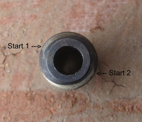
Worms are typically made in 1, 2, or 4 start configurations.  A traditional worm gear must be cut to match the number of starts on the worm.  When cutting an angled spur gear to substitute for a worm gear, it makes no difference how many starts on the worm.  What's important is the angle of the teeth and this is determined by measuring the angle of the threads on the worm.


The number of starts on the worm, along with the number of teeth on the gear will determine the ratio.  A 40 tooth gear with a single start worm results in a 40:1 ratio.  A 40 tooth gear with a double start worm gives you a 20:1 ratio and a 40 tooth gear with a 4-start worm gives you a 10:1 ratio.

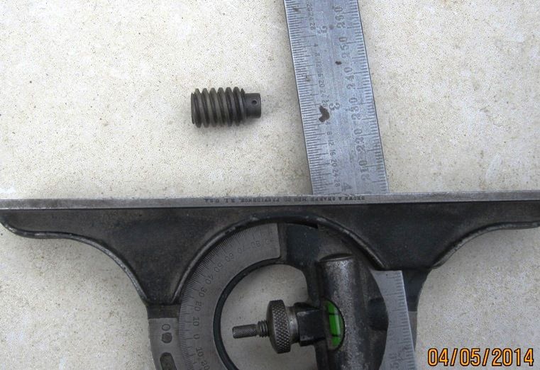
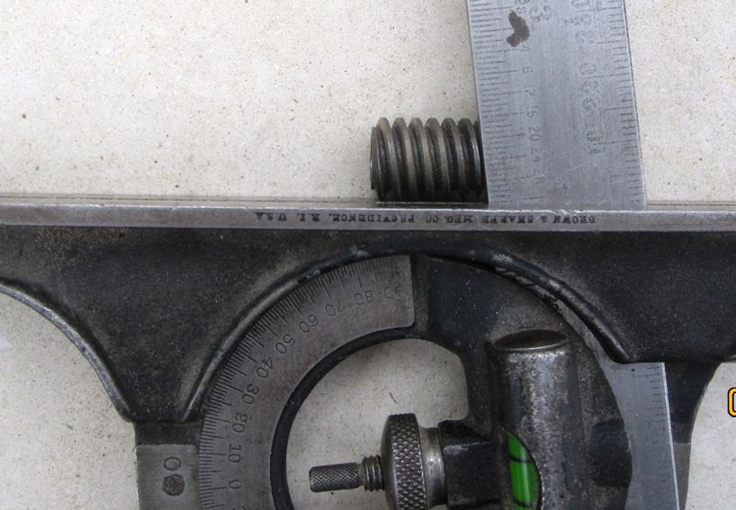
The worm I am using has a 6.5 degree angle on the thread.  So, I need to set my dividing head at 6.5 degrees off parallel before cutting the teeth. 
Do do this, I measured and cut a sliver of MDF. 


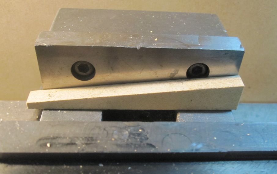
To do this, I first used my table saw to crosscut a long piece to 90 degrees.  Then I set my mitre gauge to 83.5 degrees and cut off the sliver shown.

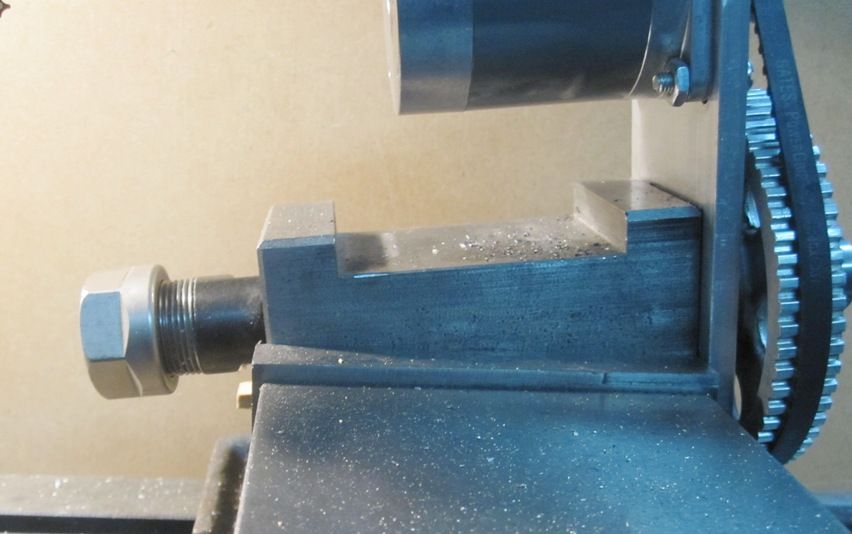
Here is the dividing head clamped in my vise, resting on the sliver of MDF.


From here, the process is just like cutting a regular spur gear.  Cut a tooth (groove), rotate the blank, cut another tooth, etc.  As long as your angle is less than about 7 or 8 degrees, you can use the normal calculations for the pitch diameter, the overall diameter of your gear blank, and the number of the involute gear cutter you need to use.   If the angle is much greater than that, you need to start using helical gear cutting calculations.

Hope this helps...

Chuck
So many projects, so little time...

Offline Johnb

  • Full Member
  • ****
  • Posts: 167
  • John Browning, IDSME
Re: Worm Gear Substitute
« Reply #3 on: April 05, 2014, 10:36:37 PM »
Interesting Chuck. Thanks for that. I'm in the process of cutting a single start worm to match with 64 teeth, 32DP bull wheel on my Cowells lathe. The worm required a 10.186 TPI thread and by calculation, I used 70 and 55 tooth changewheels on the club's Myford to cut it (my Cowells is a plain lathe). The calculations were done as per Ivan Law's "Gears and Gear Cutting" using a calculator, though I'm sure there will a spreadsheet out there somewhere that takes the grunt out of it. I enjoyed the calculation exercise, but then I always was a bit odd! Since the worm has to mesh with a straight cut worm wheel (the bull wheel), the axis of the worm is offset by the lead angle, which for a half inch worm worked out to 3.3 degrees.
My first attempt meshed and drove the bull wheel as required, but the thread angle on the tool was wrong so there was more backlash than I wanted. I'm just about ready to have another go having resharpened the tool to the correct form. As and when I get a chance to cut it, I'll post some pictures.
John Browning. Member of Ickenham and District SME


SimplePortal 2.3.5 © 2008-2012, SimplePortal