I made some valves trying closely to follow a procedure spelled out in an
excellent sequence of words and pictures in the build of gbritnell's
5-cylinder radial (on another site).
While I did create at least 2 valves that would surely have worked, I was
unhappy, mostly about the finish I got on the stem and the trouble I had
getting a smooth transition from stem to seating face. The material is 303
stainless. I used a cutting tool with a relatively sharp point and zero
leading angle, this to try and reduce radial forces and concentrate cutting
forces axially along the stem to prevent flexing. I guess the sharp point
contributes to the less-than perfect finish, resulting in some grooves which
are not easily removed with abrasive.
I imagine a little more effort along those lines would have resulted in valves
I was very happy with, but I was also getting bothered by the repeatability of
my efforts (that 2 steps forward, 1 step back sort of feeling). In the
interest of experimentation and trial-and- error learning, I decided to pursue
the idea of a valve machining jig I saw in Issue 7 of Model Engine Builder
magazine. The article describes essentially a combined follower rest and form
tool, the form of which is to cut the underside of the valve head and the stem
at the same time. The tool described had the underside angle ground into the
cutting tool, but I took the different approach of mounting the cutter at the
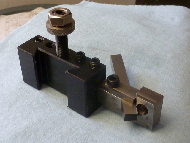
desired 45 degree angle. This made grinding the cutter much easier. Here is the
jig mounted in a QCTP holder. The cutter here has not yet been ground, but you
get the idea. The reamed hole closely fits the 3/8" stock which will be held
in a collet.
My first step closely follows George's procedure. With the stock in a collet,
I cut a short section down to stem size and cut a groove for an e-clip (the
plans call for the retainer being loctited onto the stem, but this is another
of my departures from plan). Incidentally, I ground the groove cutting tool
myself, and while it's not perfect, it helped to build my confidence in tool-
grinding. It works good enough, and I think next time I can do better! Oh, I
should mention I've gone from 303 stainless to 416 stainless. The 416 machines
better.
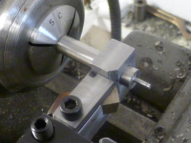
Getting the stock started into the jig is a little fiddly. The cutter is
withdrawn to get it out of the way. Once at this point, I pulled back the
cross slide just enough to feel a touch, trying to ensure that any radial
force would immediately meet resistance at the backside of the bore. I ensured
smooth operation all the way to the collet, and then slathered the stock to
the left of the jig with cutting oil. The article suggests drilling an oiling
cavity at the top, but I forgot to do that.
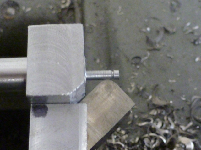
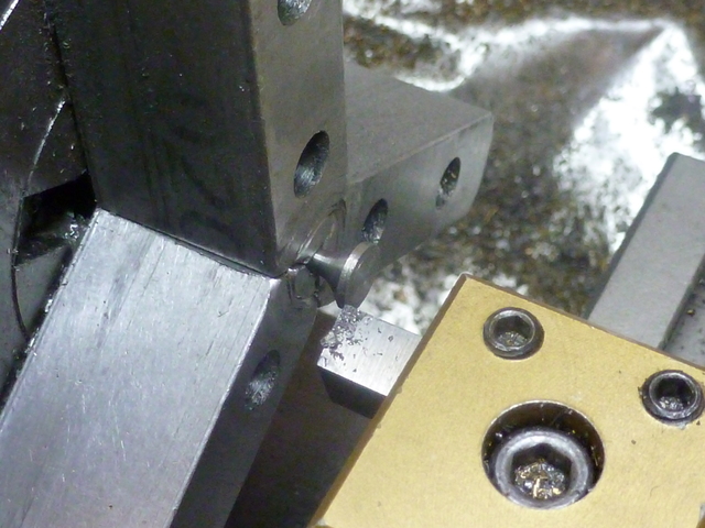
I advanced the cutter to touch the sized stem, and clamped it. Here you can
see the radius of the form tool. There is side and end relief, as well as
side -rake ground in, which is not obvious in this picture.
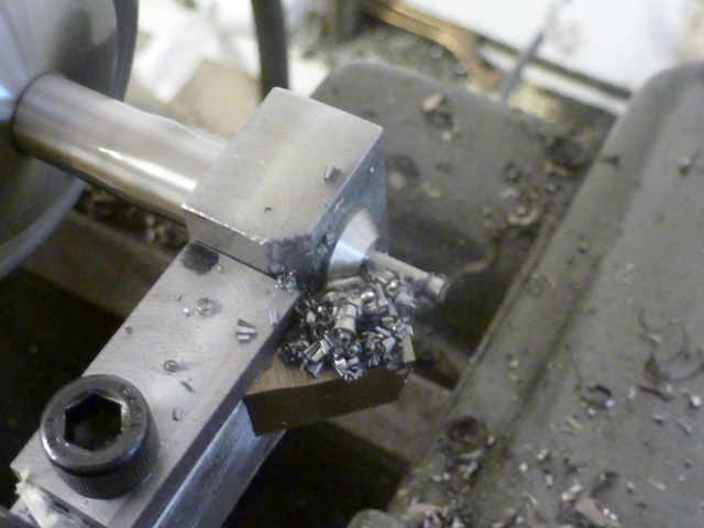
I cut with power carriage feed on the slowest gear, spindle speed somewhat
slower than I used with the sharp pointed tool. This is an action shot. There
is absolutely no chatter.
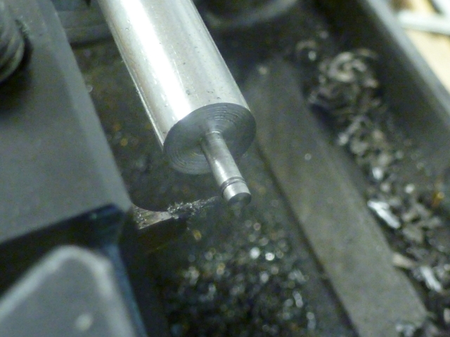
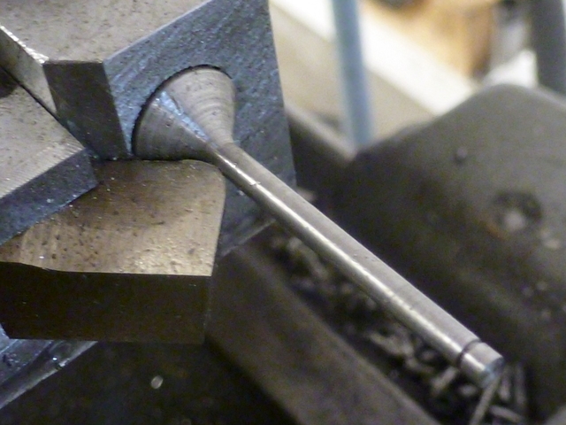
After stopping the feed, I pulled back from the work a little before turning
off the spindle (photo). Then I loosened the cutter and pulled it back some
to prevent scraping when I cranked the jig back.
I worked the stem and head underside with emery some (probably not enough),
then turned the head diameter and parted off.
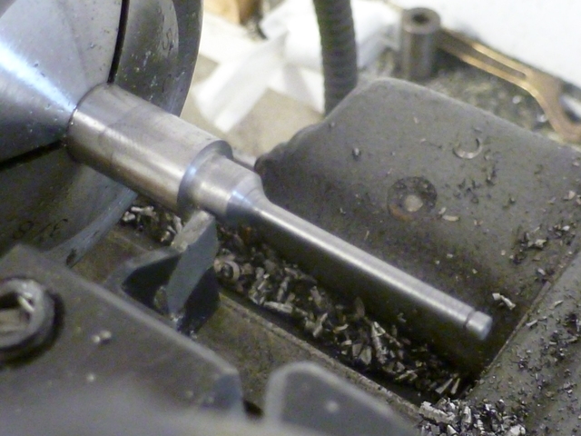
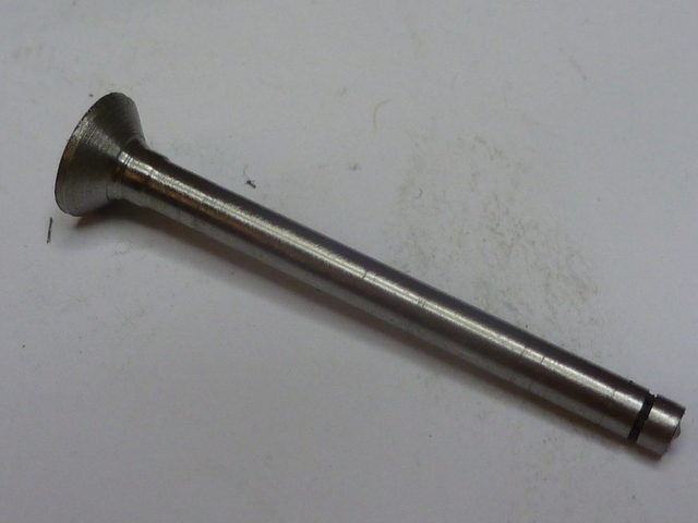
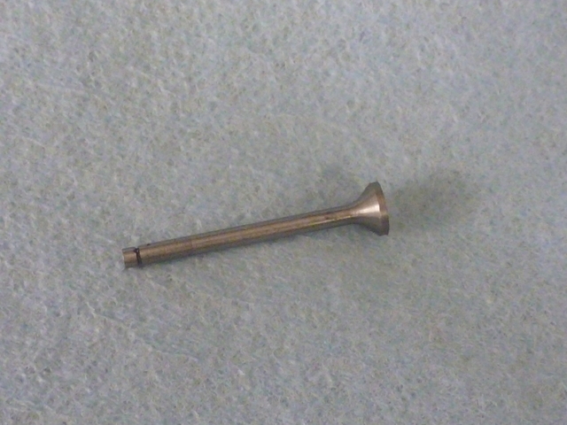
I pulled the good old Taig into service for facing the top of the head.
Here it is. Not as pretty as the one I just saw in Vince's Kiwi build, but I
think this will work. Most importantly, this process seems quite repeatable,
and I feel that the next one I make can only be better. Forward progress
does wonders for my sanity.
Having done all this, I'm still pretty sure I could have eventually
gotten equal or better results using George's method, but I'm glad I tried
this. Comments and criticisms are welcome as usual.
Thanks for looking in,
--Tim


