Well finally getting around to install my VFD on my mill. Eric this write up is mostly for you my brother since I know you have the same mill.
I start out by stripping the wiring from the old motor which was a single phase motor and installing a 3 phase one in its place. The motor was the same HP 1.5HP TEFC motor and the mounting was very close but I had to ream the foot hole some to get the bolts to start. The pulley also did not fit. So I chucked it in the four jaw chuck and cut it to .875 same as the shaft and trimmed the motor key to fit the pulley key slot. I used a 10 conductor beldon cable with shield to wire the pendant with and controls to the VFD. The whole assembly was mounted on to a Din Rail and all wired up before I install it inside the bottom compartment of the mill. The assembly was mounted all the way to the back side of the compartment towards the top to keep it clear of things should I put tools inside It, and give it more clearance to push the cable through the upper opening to the back terminal strip.
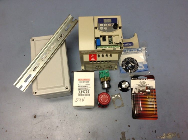
This first photo is all the parts need to do the modification with except the cables and wires.
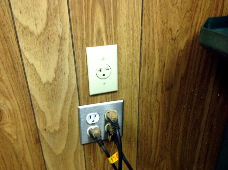
I also had to add a 240VAC 20 amp single phase receptacle since I have a 1.5HP motor the VFD needed higher voltage to operate.
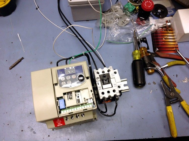
Starting to wire the main power leads to the contactor. I use the contactor for estopping the VFD by removing power to it. For securing it when I leave and just safety because the control circuit can become non operational and you wouldn't be able to turn it off.
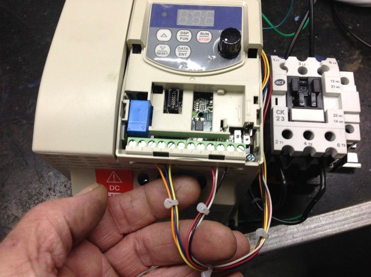
Wiring in the pendant control circuit. This has three wire for the control pot, three wires for the Fwd and Rev selector switch and two wire for the ESTOP pushbutton. The Estop will be wired in series with the Top pulley cover switch. This wire actually goes to the motor Jbox and makes its way through the motor cable flex then to the pendant. The motor leads that existed had four wires two black and two reds. You can strip one of the red lead out.
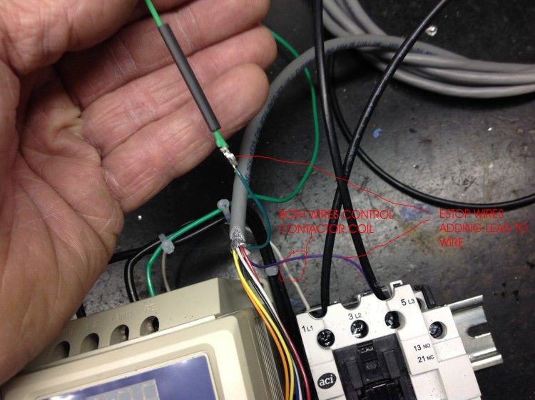
In this photo I am showing the Estop cable which are the Violet and green wire in the Beldon 10 conductor cable. I solder a wire to the green and the violet to the contact coil. Then added a white wire to the opposite contact coil circuit. This puts the Estop wires in series with the power coming in to control the contactor with the Estop.
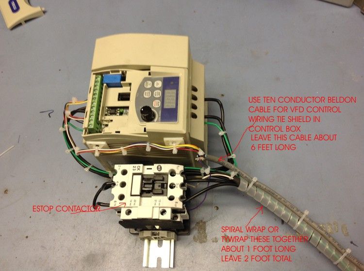
The assembly after wiring up now its ready to install into the bottom cabinet of the mill.
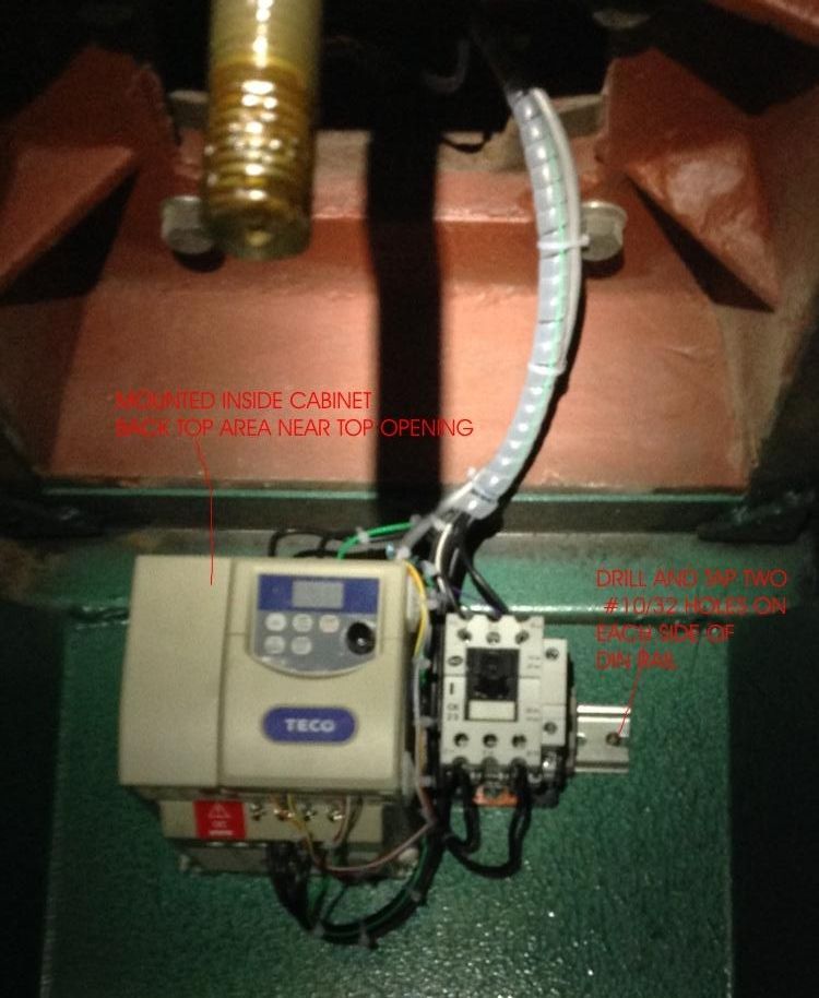
This photo shows it mounted to the back side of the compartment.
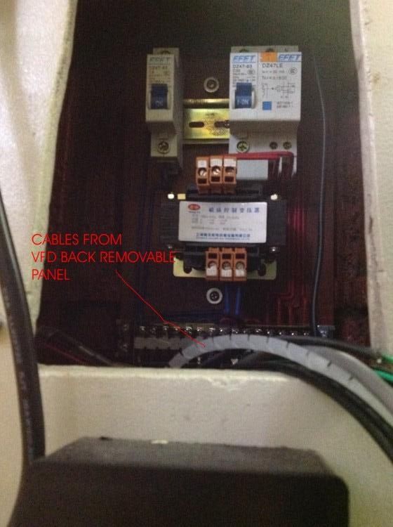
A photo of the terminal strip, transformer and circuit breakers. One circuit breaker is for the motor and the other is for the transformer. The transformer is use for the light and is 24VAC output with dual voltage input. We will use this 24VAC to control the contactor coil. So the white wire and the green wire to the Estop will connect to the transformer output.
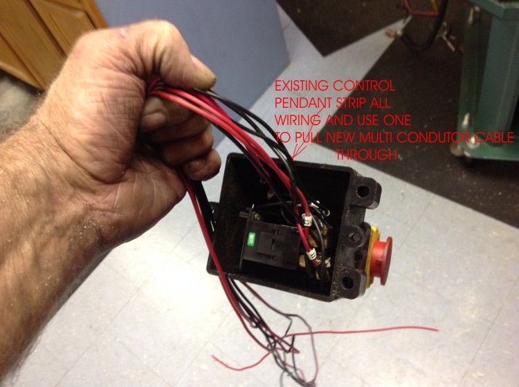
The existing pendant is now removed with all wires and we used one wire to pull the beldon multi conductor control cable through.
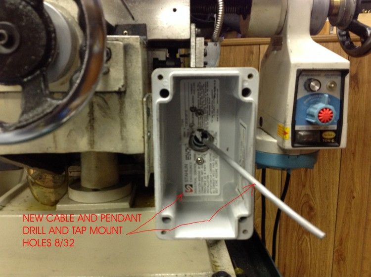
The new pendant box and new cable ready to wire.
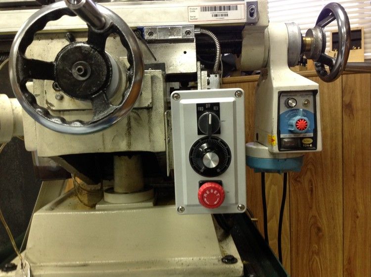
The pendant all wired and complete.
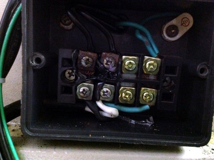
This photo is the terminal strip where the power cable tied to and do you thing I was going to have problems.
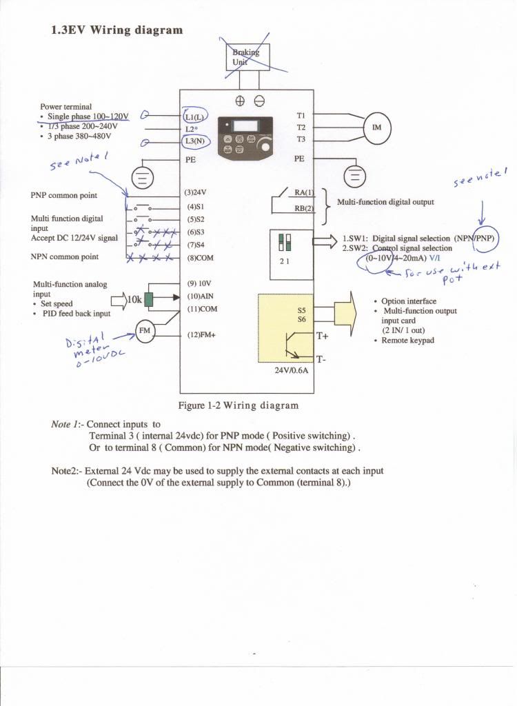
A photo of the VFD basic connection.
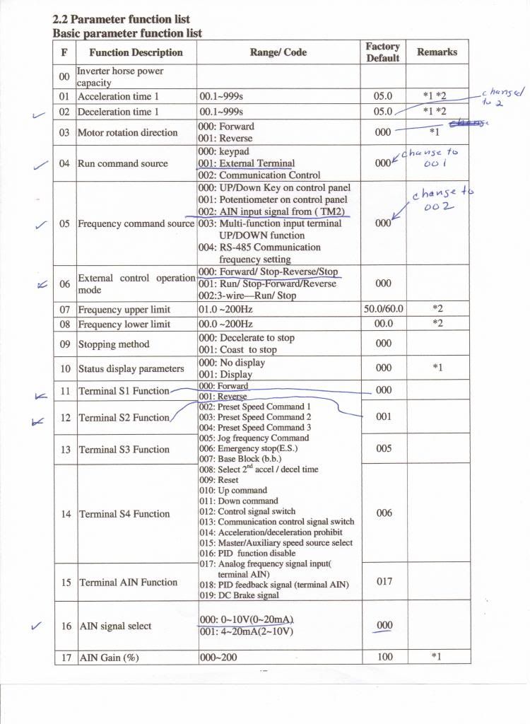
The parameter list and you can see the ones I have changed to make the remote pendant work.
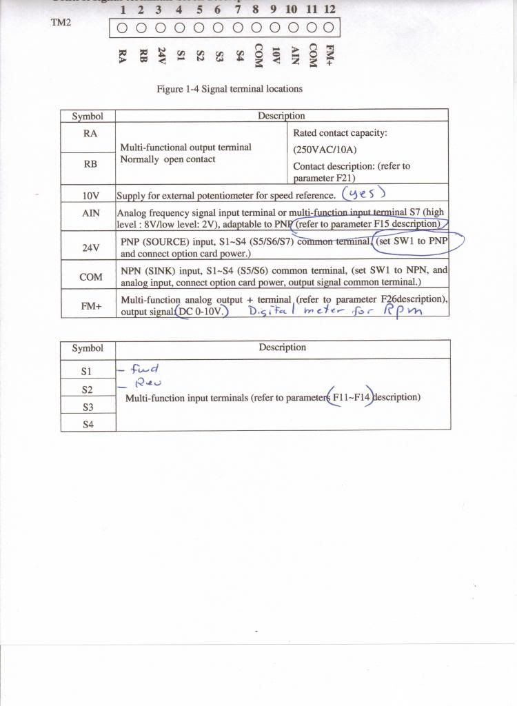
Signal terminal sheet.
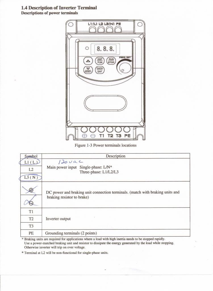
Motor power terminals.
I haven't had time to do a drawing yet but I will post it when I have it done.
If you have any question you can PM me and I will try to help you any way I can.
I will also add a step to change the parameters with.
Thanks for looking .
Don


