Author Topic: Muncaster's Joys Valve Engine  (Read 160056 times)

Offline smfr

  • Full Member
  • ****
  • Posts: 1203
  • San Francisco Bay Area, California
Re: Muncaster's Joys Valve Engine
« Reply #510 on: December 15, 2014, 07:05:58 PM »
I think rather than D shaped bosses I would go for round ones which can be screwed into fine pitch threaded holes (such as 40 TPI) these can then be tapped for the drain cocks.

If you cut the thread on the boss with a die and do it on the end of a decent length of bar you will have something to get hold of so it can be screwed in tightly and will wedge itself in a bit like a taper pipe thread, the JB Weld will seal any gaps and make sure it does not come loose.

Threading the bosses had crossed my mind; I'll have to try hard to get threads all the way to the bottom of the hole. I do have some 40TPI taps and dies luckily! Seems like it would be good to leave a length of bar sticking out from each boss to ease with tightening, then cut down after things have hardened up.

PS on those drain cocks what will stop the tapered spindle working its way loose, you probably want a nut on teh small end to keep the spindle pulled into the taper.

I had nuts there mentally, just too lazy to model them :)

Simon

Offline Jasonb

  • Full Member
  • *****
  • Posts: 9493
  • Surrey, UK
Re: Muncaster's Joys Valve Engine
« Reply #511 on: December 15, 2014, 07:26:27 PM »
I was thinking of drilling and tapping right through to the bore, it looks like the hole would not go much further into the bore than the slot for the steam passage so provided your piston packing did not catch the edge of the hole there is no need to do a blind hole.

You could make them a bit like this as they won't show that way you have a smaller dia hole into the cylinder wall which won't come as close to the piston packing and a longer thread length/dia ratio a 3/16x40 thread would be enough as the drain hole only needs to be 1/16"

J

Offline kvom

  • Full Member
  • *****
  • Posts: 2649
Re: Muncaster's Joys Valve Engine
« Reply #512 on: December 15, 2014, 11:02:09 PM »
Unless you are going to run high pressure steam you should be able to use soft solder.  30psi steam is 275F.

I was a bit surprised that you hollowed out the bottom of the cylinder, since you will need a sub base to clear the flywheel.  Your exhaust tube could have been routed to the sub-base.  Same applies to cylinder cocks if you need to route the drains using copper tube.

Offline smfr

  • Full Member
  • ****
  • Posts: 1203
  • San Francisco Bay Area, California
Re: Muncaster's Joys Valve Engine
« Reply #513 on: December 15, 2014, 11:38:27 PM »
Unless you are going to run high pressure steam you should be able to use soft solder.  30psi steam is 275F.

I was a bit surprised that you hollowed out the bottom of the cylinder, since you will need a sub base to clear the flywheel.  Your exhaust tube could have been routed to the sub-base.  Same applies to cylinder cocks if you need to route the drains using copper tube.

I hollowed the bottom of the cylinder block to reduce thermal mass, and to make it more like a casting, but I wish I'd thought about drain cocks before I did it.

You're right that I could have taken the exhaust and drain cocks out through the sub-base, which would have given a neater appearance. Wish I'd thought of that now!

Simon

Offline smfr

  • Full Member
  • ****
  • Posts: 1203
  • San Francisco Bay Area, California
Re: Muncaster's Joys Valve Engine
« Reply #514 on: December 29, 2014, 05:35:15 AM »
You're right that I could have taken the exhaust and drain cocks out through the sub-base, which would have given a neater appearance. Wish I'd thought of that now!

I'm thinking of plugging the hole I made in the base and doing what you suggest, Kvom, but we'll see what kind of base I come up with later.

My job over the past few days has been to deal with the cylinder drain cocks, using Jason's suggestion of threaded plugs. I turned some bits of scrap cast iron into little plugs:


which then had a 1/16" hole drilled down the middle. Then I milled a flat spot and some clearance on the underside of the cylinder block:


This intersected one of the cylinder block stud holes, but that's OK.

Then I spot-drilled, and drilled through to the bore for 3/16 40TPI (ME), and threaded:


The threaded ends of the plugs were carefully taken down until they just cleared the cylinder bore, testing with one of my bore gauges:


A little bit of filing took off the burrs from threading.

The plugs were then fixed in with J-B Weld (continuing to contribute to Jason's retirement fund :) ), screwed them down snug, and left for 48 hours to fully cure. I then sawed off the excess (I thought a saw would have less sideways force than milling them off):


and milled flush with the rest of the "casting":


These holes were then drilled and threaded 5/32 40TPI, taking care not to drill so deep that it would separate the threaded portion from the body of the plug.

Now we move onto making the drain cocks. The cones and a matching D-bit reamer have to be made with the same taper, so the topslide was set at an angle (about 4.5deg), and the cones turned on each end of bits of brass bar:


and a bit of O-1 drill rod turned in the same setup, which you can see in the bottom of this photo. I made some spare cones, to avoid having to try to repeat the same taper setup:


As you can see, I also roughed out four drain cock bodies.

To prepare the D-bit reamer, half of the thickness was milled away:


then it was hardened by heating to red hot, then plunging into water. Finally it had a meeting with the india stone to hone the edge.

The second cutter required was a profile tool for the globe of the drain cocks, cut from a bit of gauge plate at a bit of an angle (to provide some relief on the cutting edges):


and, after hardening, this was used to profile the drain cock bodies:


Now we're ready to put that D-bit reamer to use, after drilling a hole equal to the small end of the cone diameter (about 1/8"):


after which we clean up the burrs on both sides with an end mill (the part was held in a square collet block, making it easy to flip it over):


While the cones were still attached ot their parent stock, they were matched with one of the bodies, then lapped in using some very fine Timesaver, followed by Brasso.


It seems pretty hard to get a good smooth mating finish on these conical parts, since there's no sideways movement, but I think the fit is good enough to avoid leaks.

With the cones lapped, they were then parted off, and the ends cleaned up with a little fixture that had a matching tapered hole and a recess in the back:


Now the bodies were threaded. It's a bit hard to see, but I've ground down the back of that die to be able to cut threads closer to a shoulder. I only wish the dies came this way!


The cones could then be fitted to their respective body (after some fussing around making small nuts and washers) for drilling the center hole:


Finally the cones were parted from their parent stock, and after careful parting off of some Al washers to specific thicknesses, we have all four drain cocks fixed to the cylinder block:


Next comes the linkages that gang these pairs together. I'm a little concerned that the tails of the cones on the frontmost pair might be too skinny to provide sufficient torque to turn the backmost pair, but we'll see!

Thanks for following along!

Simon

[Edit: added a couple more photos]
« Last Edit: December 29, 2014, 04:26:46 PM by smfr »

Offline fumopuc

  • Full Member
  • *****
  • Posts: 3261
  • Munich, Germany, EU
Re: Muncaster's Joys Valve Engine
« Reply #515 on: December 29, 2014, 06:30:35 AM »
Hi Simon, good to see you in the shop again. These drain cocks seems to be a high tec solution. Congratulation, they are very well done.
Kind Regards
Achim

Offline Jasonb

  • Full Member
  • *****
  • Posts: 9493
  • Surrey, UK
Re: Muncaster's Joys Valve Engine
« Reply #516 on: December 29, 2014, 07:53:23 AM »
Looking good, J

Online Jo

  • Administrator
  • Full Member
  • *****
  • Posts: 15305
  • Hampshire, england.
Re: Muncaster's Joys Valve Engine
« Reply #517 on: December 29, 2014, 08:19:10 AM »
That was a very good write up on making drain cocks Simon  8)

And the finished parts look just as good  :ThumbsUp:

Jo.
Enjoyment is more important than achievement.

Offline ths

  • Full Member
  • ****
  • Posts: 1801
  • Kangaroo Valley, NSW, Australia
Re: Muncaster's Joys Valve Engine
« Reply #518 on: December 29, 2014, 09:10:50 AM »
Hi Simon, I've felt the same way as you about honing mating tapers before, but not having Timesaver, I just used Brasso. Nice write up, good photos (as usual), and seeing you made it, it'll work fine. All the best for the new year, Hugh.

Offline smfr

  • Full Member
  • ****
  • Posts: 1203
  • San Francisco Bay Area, California
Re: Muncaster's Joys Valve Engine
« Reply #519 on: January 19, 2015, 05:19:58 AM »
Well, that first set of drain cocks didn't leave enough clearance under the top plate for the linkages, so I've been remaking them a bit longer, and to a higher standard. So I've not been idle, but haven't got much further than the state of the first set yet. Hopefully I'll have a couple of evenings this week to get some progress to show.

Simon

Offline ReFlad

  • Full Member
  • ****
  • Posts: 55
Re: Muncaster's Joys Valve Engine
« Reply #520 on: January 19, 2015, 01:53:51 PM »
Simon,
Very impressed with the quality of your work.  A true craftsmans.  Very nice build.  Thanks for showing, as I have learned so very much from you.

Ronald

Offline smfr

  • Full Member
  • ****
  • Posts: 1203
  • San Francisco Bay Area, California
Re: Muncaster's Joys Valve Engine
« Reply #521 on: February 16, 2015, 06:06:35 AM »
It's been far too long since my last update  :stickpoke:
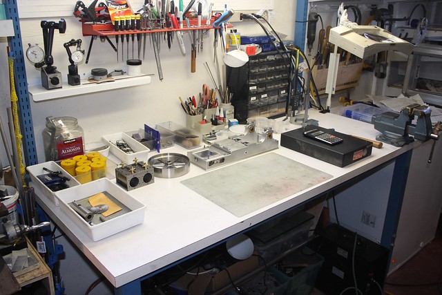
, due to a combination of weeding in the garden, engineering of the software variety, and putting up some shelves in the garage which was a good excuse to clean the workbench:


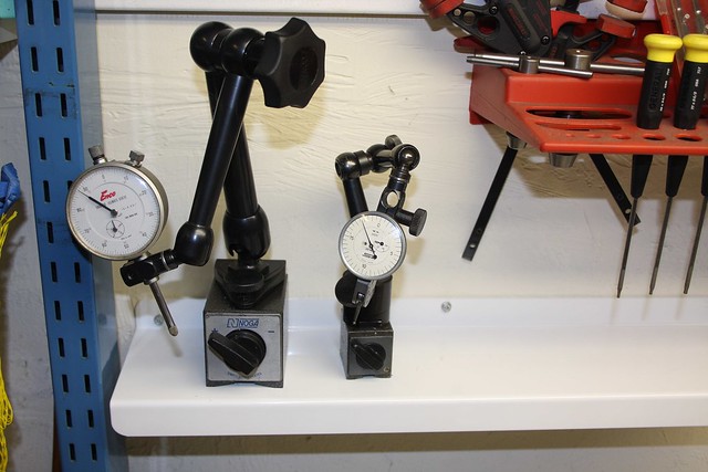
One thing I got done which I've been planning for a while is to find a metal shelf to hold the indicators. I found this metal shelf by Umbra at the Container Store ($12), and it's perfect:


Back to the engineering! As I mentioned before, I really wasn't happy with the first set of drain cocks, particularly because they all ended up at different heights, necessitated by the washer thicknesses required to have them all line up. Not only was this unsightly, but caused problems for the joining links. They were also too short, lacking clearance with the underside of the top plate of the base.

So we start again on the drain cocks, using some slightly different techniques so that they match better.

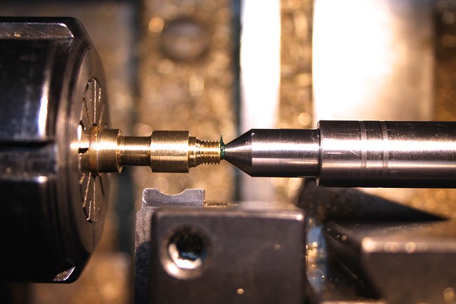
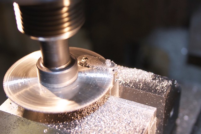
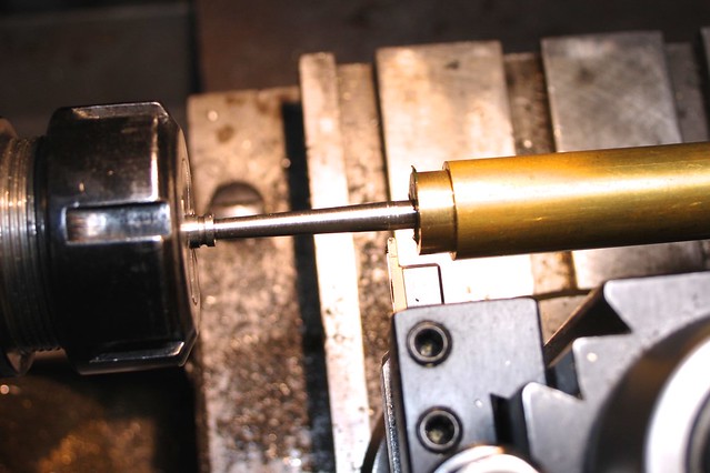
First, instead of cutting the globes when they were still attached to the parent stock, I parted each one off after some rough shaping, threaded the base and drilled through, and then set each one up with its Al washer in a fixture which was unmoved between the four parts. This required a bit more end support when applying the form tool, so a taper was cut on a bit of 1/2" drill rod to act as a dead center:


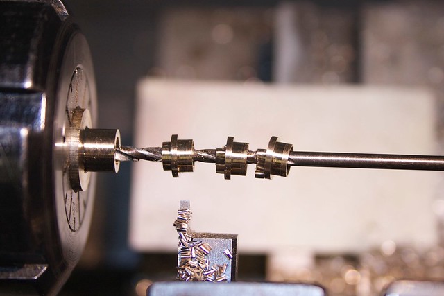
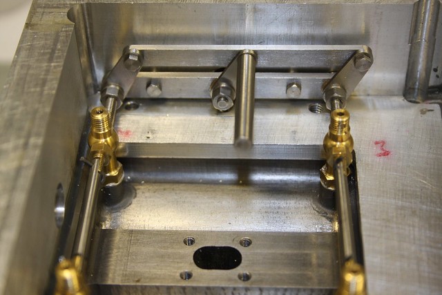
That gave me four (oops :hammerbash: three, with one of the older ones at the top) matching parts:


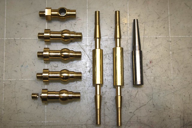
Of course all the tapers have to match, so that required a new set of spindles and a taper D-bit too.

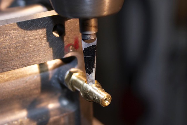
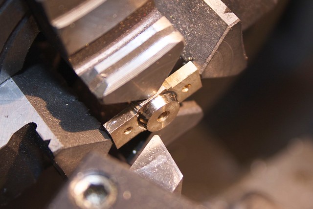
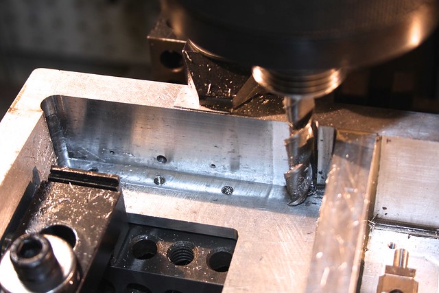
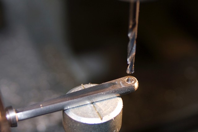
To make sure they all line up, they were drilled and tapered in situ:


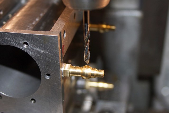
with a line on the taper tool to get an accurate depth:


Mucking around with tapers and globes is a sure way to test your accuracy; the reasonably even band of the flat here shows that my hole is pretty well on the center of the globe, which is good  ;D


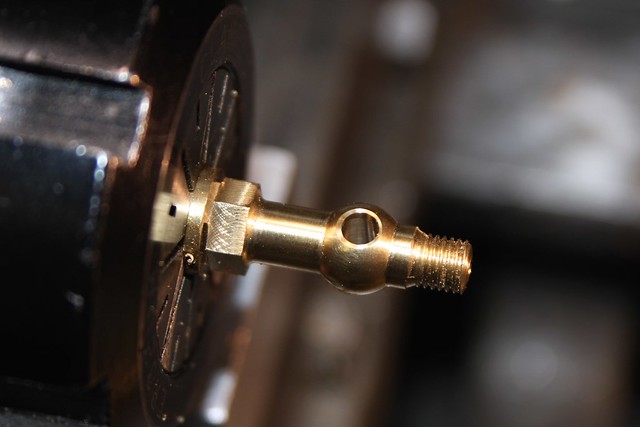
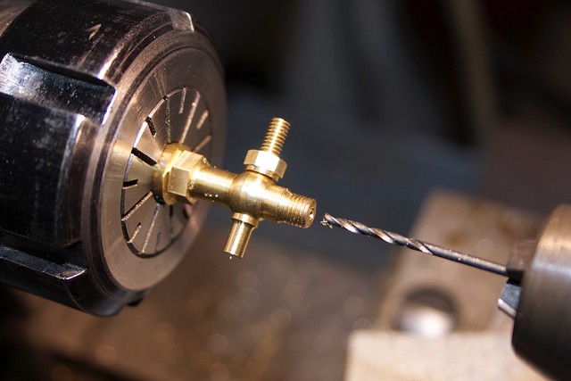
Once again a spindle is matched to each part, and drilled through:


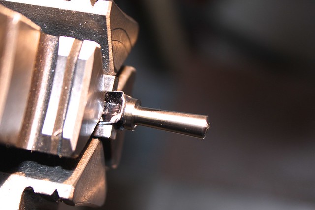
Here's another "do it better the second time" thing. The spindles need various cuts parallel to the drilled hole, and on each end, so I made this little square fixture, with a central hole cut with the tapered D-bit, and a cross hole to pick up the steam passage in the spindle.


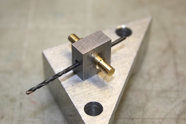
This allowed me to work on one end, then flip it around and work on the other (rather than the end being buried inside a collet). One end gets a cross hole and then a slot with a saw:


and the other a cross hole and some thinning.

A couple of bits of 1/8" SS and things are starting to come together:


There's a bit of slop in those pin holes, to allow the tapers to move as they are tightened up.

Now to the linkages that open and close the drain cocks.

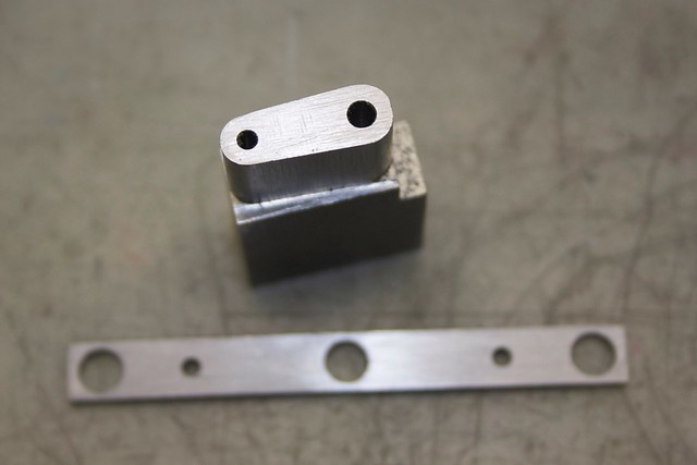
I decided to go for a handle on the outside, riding in a bronze boss, connecting to a parallel linkage on the inside. First, the "frame" for the parallel linkage is a bit of bar with three holes which will have bronze bearings, and two stud holes (lower in photo):


You can also see there a bit of SS tapered and drilled for the "arms" of the parallel motion. I think this was a bit of 304, so a bit of a bear to machine. The thinner slitting saw certainly veered off a bit  :wallbang:


but a thicker blade worked fine:


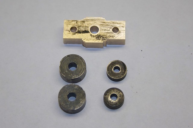
The small bronze bearings are a simple turning job:


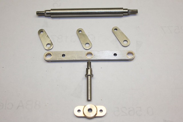
The hole at the big end of those arms was filed square, and some matching squares milled on the rod that transfers through to the handle, and then the two rotating parts at each end:


Here's a family shot which shows the parts better (before filing the holes square); the top bar has a proto part on each end.


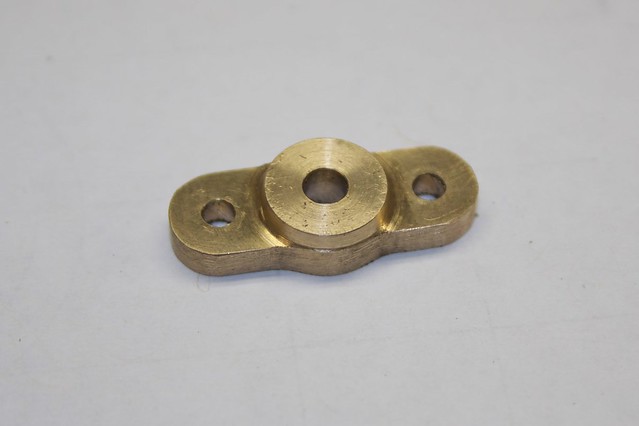
A pleasant diversion was the make the bronze boss for the outside, which started as a small bronze offcut, drilled for the spindle and two stud holes, and some filing buttons at the ready:


A bit of bar though the middle hole helps with setup:


and then we can turn a nice bevel on the front:


and after a bit of filing:


I like how it came out  :D


It needs a bit of a recess on the sloping face of the "casting":


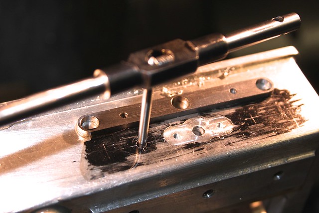
and because I can't drill from the inside, I drilled and tapped two through holes which will take screws to hold that "frame" to the inside surface:


Those will get capped off later. The inside need a bit of squaring up, and some clearance for the linkages at the end:


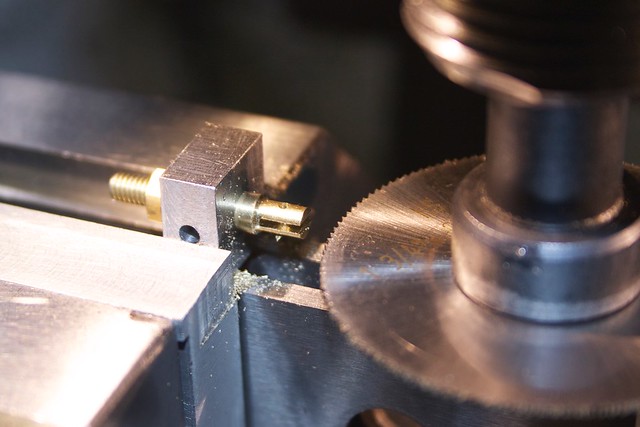
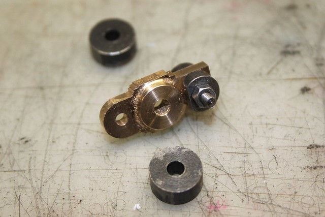
The parts that transfer the torque from the parallel motion to the drain cocks were fiddly little blighters, and had to be remade a couple of times. Working out the order in which things fit together resulting in some rather unconventional nut placement. Here I'm parting off one of those bits:


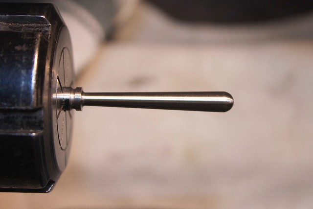
Making handles is always fun! We start with a bit of 303 SS 1/4" bar, and cut a nice taper for the shaft of the handle. This required a bit of 3/4" brass with a center drill hole in the end as a dead center:


After a bit of a polish:


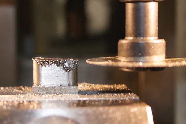
Now we take a bit off each side:


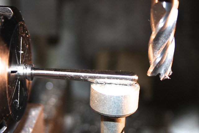
and, while it's centered, drill the hole at the end:


This is then flipped around and held (rather awkwardly) in the 4-jaw so the handle part can be done at the other end:


That hole is then filed square to take the square part of the spindle that passes through the side of the casting:


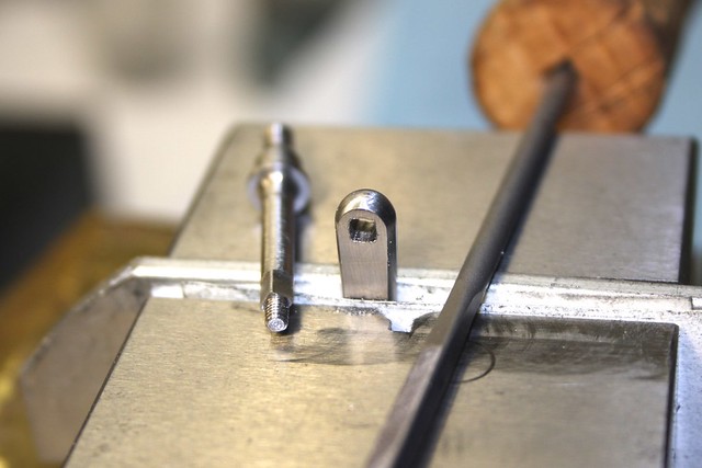
So here's what it looks like on the outside:


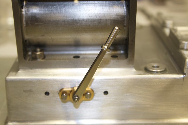
I made sure that the handle travels about 90deg, roughly even on each side, between the open and closed positions. The linkage in the inside is very much not prototypical:


but quite functional. However, it's a bear to assemble! Initially I realized it was unassemblable :facepalm2:, so I had to take a burr to the base casting on the inside to add some clearance necessary to get the parts into place. I must have spent about an hour to get it all together, and the assembly order has to be very specific, but finally managed to persuade all the tiny parts into place.

Here's a short video of the motion:

<a href="https://www.youtube.com/watch?v=fdevEJur2ik" target="_blank">http://www.youtube.com/watch?v=fdevEJur2ik</a>

It feels like it's ages since I've had this engine assembled and running, so after a few remaining odds and ends with this mechanism, I can finally get back on the home stretch, and think about a base and painting.

Thanks, as always, for following along. I hope the next update won't be quite so delayed!

Simon

Offline Jasonb

  • Full Member
  • *****
  • Posts: 9493
  • Surrey, UK
Re: Muncaster's Joys Valve Engine
« Reply #522 on: February 16, 2015, 07:57:15 AM »
Looks good Simon, I've always wondered why they used a cock on each end of the cylinder and not just take pipes to a common valve, would have made your job a lot easier :-\

Offline Stuart

  • Full Member
  • ****
  • Posts: 1785
  • Tilchestune UK
Re: Muncaster's Joys Valve Engine
« Reply #523 on: February 16, 2015, 09:17:48 AM »
Jason

If you only used one valve piped to each end it would breath though the pipe and not get full cylinder pressure each side

Think of it as a bypass to the piston

One at each end is the only way , of course they can be remote from the cylinder but a valve for each end is required.

If you use piston valves drain cocks and mandatory else you will blow the ends of the cylinders off due to hydro lock , a slide valve will lift , you will also need Drain  cocks on the piston valve Also one in the middle making five for a single cylinder

Stuart
My aim is for a accurate part with a good finish

Offline ShopShoe

  • Full Member
  • ****
  • Posts: 462
  • Central Iowa, Central USA
Re: Muncaster's Joys Valve Engine
« Reply #524 on: February 16, 2015, 02:07:56 PM »
Simon,

I enjoyed the whole saga of the drain valves.

I have been mentally working out construction of lever linkages for a future project and also thinking about valves, so your writeup of this has sent me off in some new directions.

Thanks for posting.

--ShopShoe


SimplePortal 2.3.5 © 2008-2012, SimplePortal