Author Topic: Muncaster's Joys Valve Engine  (Read 159870 times)

Offline NickG

  • Global Moderator
  • Full Member
  • *****
  • Posts: 1430
Re: Muncaster's Joys Valve Engine
« Reply #420 on: August 11, 2014, 09:15:15 PM »
That's Majestic, well done Simon you must be chuffed.

Offline vcutajar

  • Full Member
  • *****
  • Posts: 2555
  • Marsascala, MALTA
Re: Muncaster's Joys Valve Engine
« Reply #421 on: August 12, 2014, 05:29:03 AM »
Excellent work Simon.  You must be pretty happy with yourself seeing coming to life.

Vince

Offline smfr

  • Full Member
  • ****
  • Posts: 1203
  • San Francisco Bay Area, California
Re: Muncaster's Joys Valve Engine
« Reply #422 on: August 12, 2014, 05:42:30 AM »
Thank you all for your comments! I am quite chuffed to get it to this point. I'll be even more chuffed when I have it ticking over slowly without having to hold onto anything or hear any bad noises  ;D

I do have to reposition a hole in the base, so they will be some more base hacking and JB-Weld in the not-too-distant future. I also have to decide what to do about the slides and oil wells, given the interference found earlier  :thinking:

So the adventure will continue for a while yet!

Simon

Offline smfr

  • Full Member
  • ****
  • Posts: 1203
  • San Francisco Bay Area, California
Re: Muncaster's Joys Valve Engine
« Reply #423 on: August 14, 2014, 06:53:32 AM »
Thanks for all the encouraging comments, everyone!  :cheers:

To tie up the loose ends on the valves we need a couple of SS sleeves, which were a simple turning and drilling job:


and then I needed 4 SS washers which are a breeze to make:


Just one tip here; after starting the parting off groove, I back off and ease the newly cut edges with a small file, then continue to part off.

The valves ends needed a bit of relief cut for the washers and nuts:


and here are the resulting bits:


The length of the sleeves has been adjusted to be just a hair longer than the body of the valve, so that the valves move with the valve rod, but have some up and down float.

Simon


Offline smfr

  • Full Member
  • ****
  • Posts: 1203
  • San Francisco Bay Area, California
Re: Muncaster's Joys Valve Engine
« Reply #424 on: August 18, 2014, 04:37:55 AM »
After three days in the shop over a long weekend I accomplished a few more bits and pieces.

Those poor square valve rod glands needed drilling for studs:


and shaping with some hardened filing buttons (note how the central button needed some bites taken out to make space for the smaller buttons)


I also received a shipment from Chronos which included some nice HSS BA dies. The 7BA die cut the threads on these 303 stainless studs like a dream, so much better than the Tap & Die HQS dies I was using before.  :cartwheel:


The 4BA die even allowed me to make some stubby studs for the piston rod glands:


and cut well enough that I could hold the stud in a collet, without having to resort to the stud holder!  :pinkelephant:

Another easy job was to cut some gaskets. I have some "oakenstrong" paper that came from Stuart Models from an earlier build, and I like to clamp the part down over it on the bench, then cut around the edges with a sharp craft knife.


The holes are cut using some home-made punches, turned from O-1, shallow-drilled in the end and then brought to a sharp edge with a countersink:


This was then hardened and tempered. It cuts clean holes in the gasket material with the tap of a hammer.

Simon


Offline smfr

  • Full Member
  • ****
  • Posts: 1203
  • San Francisco Bay Area, California
Re: Muncaster's Joys Valve Engine
« Reply #425 on: August 18, 2014, 05:04:22 AM »
Now we have some parts to make for the valve control handle. This attaches to the side of the engine, and turning the shaft via a hand wheel at the top raises or lowers the end of a connecting link which is fixed via a key to the curved guides assembly made earlier. So I made the easy parts first  :D

These consist of the main shaft of this control assembly. This started as a length of 1/4" 303 SS. The top 1-3/4" were turned down and threaded 3/16"-32TPI using a die (I chose a coarser thread than the appropriate BA size, since a finer thread would make going between forward and reverse too laborious).

The central section is turned down with decorative radii on each end:


and the bottom end needs a section turned down to 3/16", then some threading for a 4BA nut:


Now we need to make a couple of right-angle linkage doodads, which I chose to do by silver-soldering. I turned down a couple of bits of 3/8" rod to give a 11/32" section (the final diameter of the parts here) but leaving enough to grip in a collet. Then the cross-pieces, some short sections of 11/32", need a side bored out to fit at right angles. I started with an end mill:


then bored to size with the small boring head:


since I don't have an 11/32" end mill :shrug:

This probably makes more sense once you see the pieces:


You can see that I've made some punch marks to leave room for solder flow, and hammered out some bits of 56% silver solder to put between the parts.

Here we're set up for soldering:


I did a couple of things to help keep the parts in place. First, I gouged a depression in the refractory brick to prevent the part from rolling around, and second I made one of those "one-legged bird" props that you all started  ;D to use to weigh things down (it's the bit of wire on top of the part).

I was quite pleased with the result; the metal here is 303 stainless, so I was a bit worried about the solder not wetting, but it worked well and I got a nice fillet:


One part didn't get a full fillet:


but after finish machining it's hardly noticeable.

These could then be set up in the square collet block, dialing in around the circumference of the vertical part:


and now we can drill and ream the cross holes knowing that they are perpendicular to the main axis:


I did some passes with an end mill to take the vertical section to length too. That leaves us with:


Back in the lathe I can now take the ends down to size:


and finally the part is parted off:


Here they are with the control shaft:


and here's where it goes on the engine:


Now that hole in the base with the drill bit sticking out is actually in the wrong place  :facepalm: Muncaster's plans are a bit contradictory on the placement of this hole, and back when I made the base I either took the wrong dimensions, or just had a brain-fart and marked it out incorrectly. I need to move it, so I'll be milling off that boss and J-B Welding another one in place at some point.

Thanks again for following along  :cheers:
Simon

Online fumopuc

  • Full Member
  • *****
  • Posts: 3256
  • Munich, Germany, EU
Re: Muncaster's Joys Valve Engine
« Reply #426 on: August 18, 2014, 05:56:04 AM »
Hi Simon, it is coming together now. I am always following along. Thanks for sharing all these details of your build with us.
Kind Regards
Achim

Online Jo

  • Administrator
  • Full Member
  • *****
  • Posts: 15305
  • Hampshire, england.
Re: Muncaster's Joys Valve Engine
« Reply #427 on: August 18, 2014, 05:59:04 AM »
Those came out well  :ThumbsUp:

Jo
Enjoyment is more important than achievement.

Offline vcutajar

  • Full Member
  • *****
  • Posts: 2555
  • Marsascala, MALTA
Re: Muncaster's Joys Valve Engine
« Reply #428 on: August 18, 2014, 07:27:43 AM »
The way you fabricate things is awesome Simon.  I always learn new things with your descriptions and photos.  Thanks

Vince

Offline Don1966

  • Full Member
  • *****
  • Posts: 6818
  • Columbia, MS
Re: Muncaster's Joys Valve Engine
« Reply #429 on: August 18, 2014, 02:17:58 PM »
Nice bit of fabrication Simon that came out real nice. Still following your beautiful project bud.


 :popcorn:

Don

Online Kim

  • Global Moderator
  • Full Member
  • *****
  • Posts: 7926
  • Portland, Oregon, USA
Re: Muncaster's Joys Valve Engine
« Reply #430 on: August 18, 2014, 03:37:29 PM »
I'll have to agree Simon, beautifully done!  That's a lot of work for a couple of little parts!
Very nice!  :ThumbsUp:  :ThumbsUp:

Kim

Online Roger B

  • Global Moderator
  • Full Member
  • *****
  • Posts: 6165
  • Switzerland
Re: Muncaster's Joys Valve Engine
« Reply #431 on: August 18, 2014, 06:15:56 PM »
Magnificent work as ever  :ThumbsUp:  :ThumbsUp:

Is the pivot for the control rod really wrong? Does it fit if you turn the right angle doodads the other way round?
Best regards

Roger

Offline doubletop

  • Full Member
  • ****
  • Posts: 362
  • Wellington NZ
Re: Muncaster's Joys Valve Engine
« Reply #432 on: August 18, 2014, 09:14:57 PM »
Magnificent work as ever  :ThumbsUp:  :ThumbsUp:

Is the pivot for the control rod really wrong? Does it fit if you turn the right angle doodads the other way round?

Roger - my immediate thought as well

Pete
?To achieve anything in this game, you must be prepared to dabble on the boundary of disaster.? - Stirling Moss

Offline smfr

  • Full Member
  • ****
  • Posts: 1203
  • San Francisco Bay Area, California
Re: Muncaster's Joys Valve Engine
« Reply #433 on: August 18, 2014, 10:39:31 PM »
Magnificent work as ever  :ThumbsUp:  :ThumbsUp:

Is the pivot for the control rod really wrong? Does it fit if you turn the right angle doodads the other way round?

Roger - my immediate thought as well

Pete

Thanks for the comments, folks!

The pivot is actually the wrong way round in the photos (I was just balancing the rod there), but turned around it's still wrong, as my CAD model shows. As designed, the control shaft is perfectly vertical when the engine is fully in forward or reverse.

Simon

Offline smfr

  • Full Member
  • ****
  • Posts: 1203
  • San Francisco Bay Area, California
Re: Muncaster's Joys Valve Engine
« Reply #434 on: August 24, 2014, 05:24:25 AM »
Onto the final moving part! This is the "valve control" link that goes between the handle and is keyed to the valve yokes assembly.

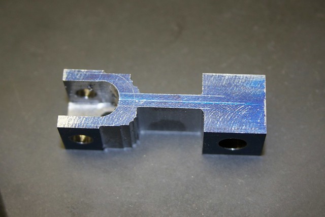
We start with an offcut of 1144SP, milled to size and marked up:


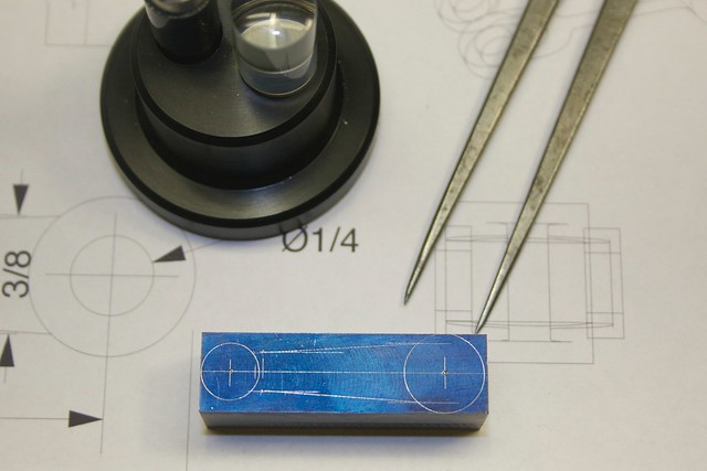
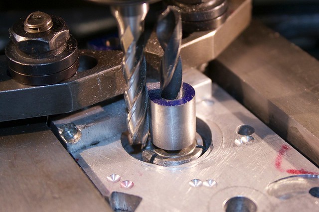
and the first thing I did was to drill and ream the holes:


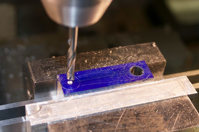
There's another sacrificial hole at right angles to those two holes, which will be used to center the part on the rotary table for turning the outside arc of the yoke.

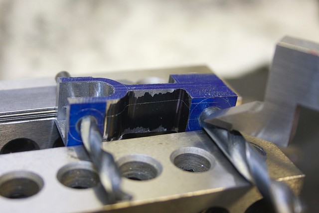
While the part is still easily held in the vise, I milled out the yoke:


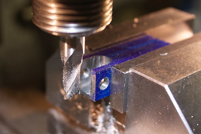
but left a bit of material on the bottom to leave that third hole. Now the sides are thinned down:


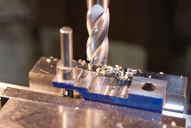
and we're left with this:


At this point we're in with a session on the rotary table. The first thing I did was to mill the outside arcs of the yoke (no photo, sorry). Now I need to mark up the taper, so I know how far to wind when rounding the ends on the rotary table. Some shims under one end give the required taper:


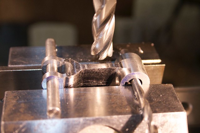
and then we can round off the big end:


That 3/16" end mill was too long for this job; I was getting some singing and poor finish, especially near the tip, but I didn't have another end mill with enough length of cut.

One end done:


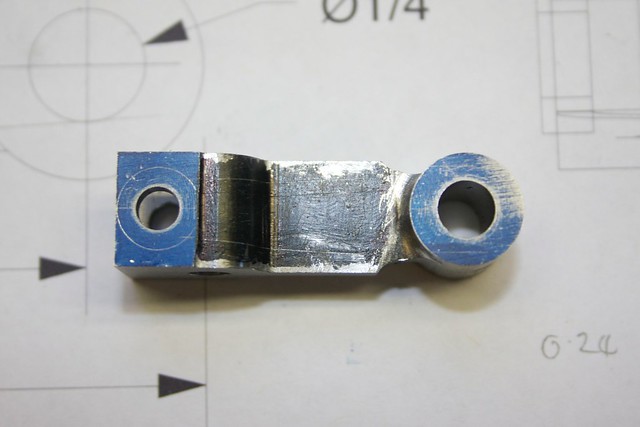
Now we can round the other, yoke end, milling away that connecting part in the process:


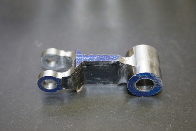
which gives us this:


While the part still has some straight edges and can be held in a vise, it's a good time to cut the keyway. I found this nice broach set on eBay, which was sold as used but the broaches still have the protective wax, and are sharp  :cartwheel:


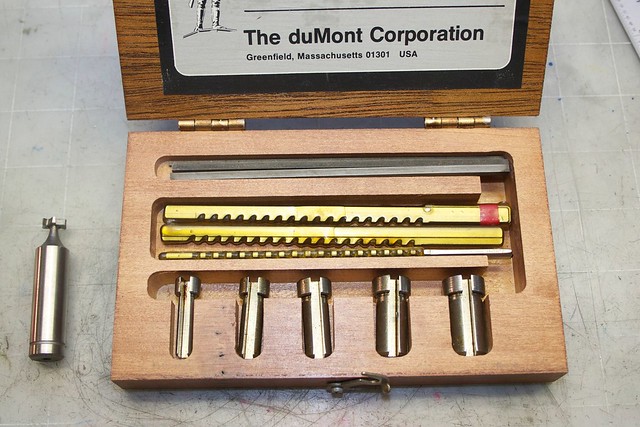
and I bought a corresponding 3/32" woodruff cutter.

After making sure the broach is lined up with the part, the keyway was cut with one pass of the tool:


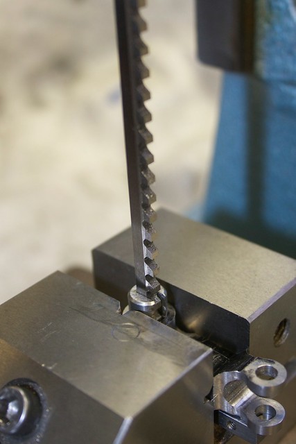
This needed quite a bit of pressure, and I had to ease the broach back a couple of times before it would start cutting with another tooth, but it wasn't too hairy. To press the broach I used a lever press that I got locally (some kind of tech lab castoff). It doesn't generate as much force as an arbor press, but worked fine for this job.

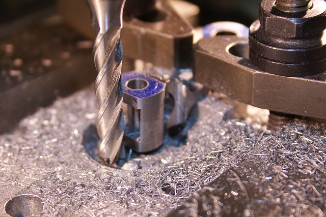
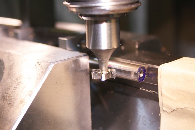
The final step was to clamp the part with some dowel and a drill bit to give the correct taper, and mill away the excess, using an end mill with a corner radius:


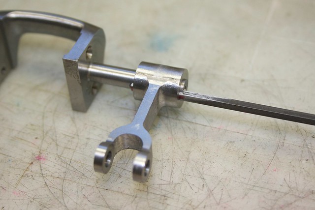
The valve yokes assembly needs a keyway cut in the shaft, so that was set up in the vise, making sure I had support behind the skinny shaft:


I touched the cutter off the top of the shaft using the "cigarette paper" method (actually some crinkly cracker wrapper which is about 1 thou thick), moved the cutter down by half of (shaft diameter + cutter thickness), and cut in several passes taking about 8 thou per pass. I worked out how deep to cut the keyway by putting a bit of key stock in the matching part, and using drill bits of various sizes to see how far the key projected into the bore.

A trial fit looks promising, with everything snug:


and finally a trial assembly:


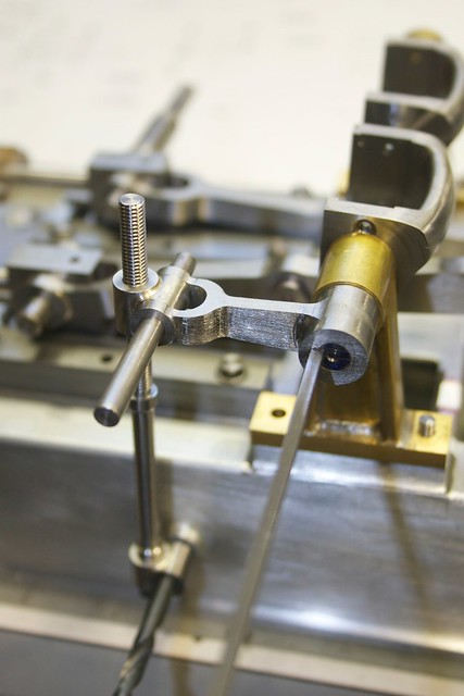
Seeing how this goes together it's obvious that I have to move the boss that the control handle attaches to, so I have various operations to do on the base next!

Thanks again for following along, and for the comments!

Simon


SimplePortal 2.3.5 © 2008-2012, SimplePortal