Author Topic: Muncaster's Joys Valve Engine  (Read 159831 times)

Offline kvom

  • Full Member
  • *****
  • Posts: 2649
Re: Muncaster's Joys Valve Engine
« Reply #390 on: August 04, 2014, 01:20:25 PM »
Dennis' version of the valve guide uses a lozenge shape with two screws like the packing gland, and specifies bronze.  Can't decide which I like better.   :shrug:

I've always wondered why this type of guide is needed.    :headscratch: In principle steam pressure will keep the valve itself against the ports, and the gland will keep the valve rod straight.  I didn't need a long valve rod and guide for my loco build.

Offline smfr

  • Full Member
  • ****
  • Posts: 1203
  • San Francisco Bay Area, California
Re: Muncaster's Joys Valve Engine
« Reply #391 on: August 04, 2014, 04:34:11 PM »
Dennis' version of the valve guide uses a lozenge shape with two screws like the packing gland, and specifies bronze.  Can't decide which I like better.   :shrug:
Interesting, mine is more faithful to the plans. Perhaps Dennis was trying to match the glands for appearance?

I've always wondered why this type of guide is needed.    :headscratch: In principle steam pressure will keep the valve itself against the ports, and the gland will keep the valve rod straight.  I didn't need a long valve rod and guide for my loco build.

There is a little sideways force on the valve rods, and I guess you'd want to avoid wearing the gland holes into ovals.

Simon

Offline smfr

  • Full Member
  • ****
  • Posts: 1203
  • San Francisco Bay Area, California
Re: Muncaster's Joys Valve Engine
« Reply #392 on: August 05, 2014, 05:51:40 AM »
I'm playing catch-up with the posting, so onto another part! The valve rods are the last part of the valve linkage that needs doing. I used 5/32" precision ground stainless, but the rods have a ring on the end that needs to be machined, so I had to silver-solder on some lumps of 1144SP.

A small step was turned on the ends of the rods to fit into a short 1/8" hole in the blocks, and they were fluxed and set up with a solder ring (56% silver) and a few small bits of solder at the bottom of the holes.


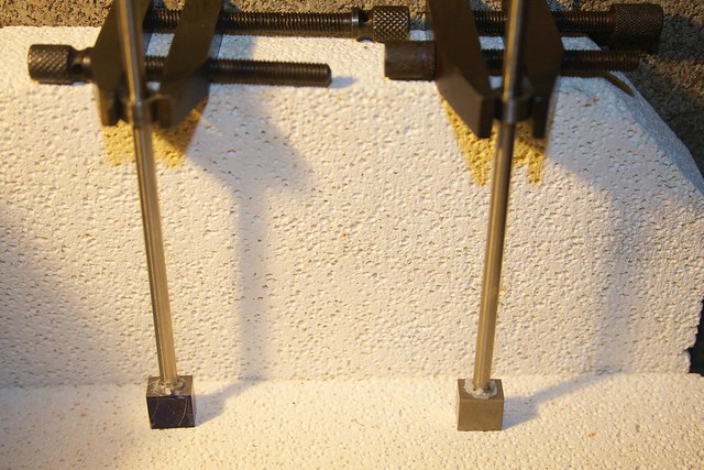
In hindsight, this wasn't the best setup; the boiling flux pushed the rods out of the holes, and they had to be pushed down. A small cross hole would have been a good idea (but would have required boring, rather than drilling the cross hole later).

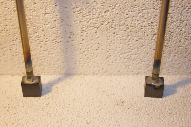
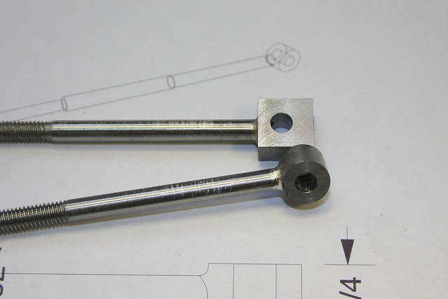
But with some twisting of the rods while the solder was liquid (which was necessary to wet the stainless) I got two mostly good joints:


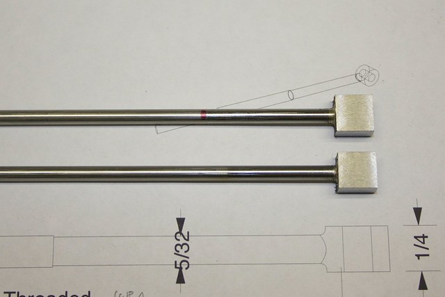
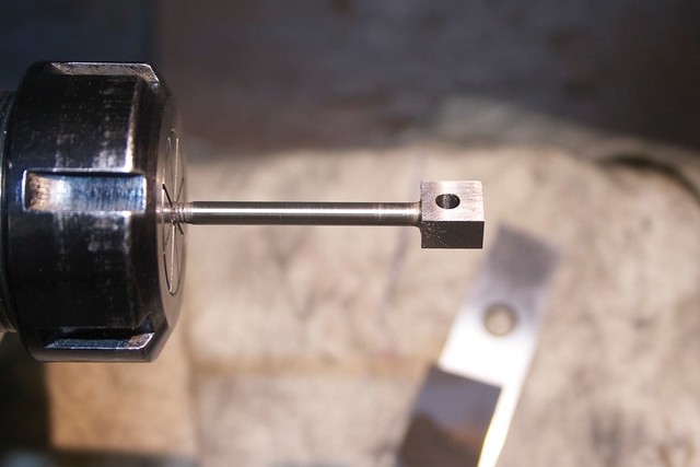
After cleaning off the flux, these went into a square collet block to square up the end lump relative to the rod with some gentle cuts:


leaving me with this:


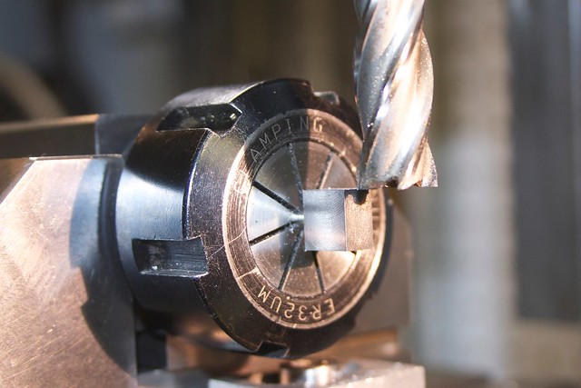
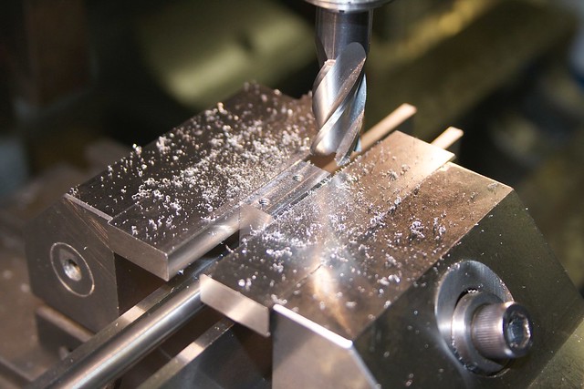
Now I could hold the blocks in the vise to drill the cross hole:


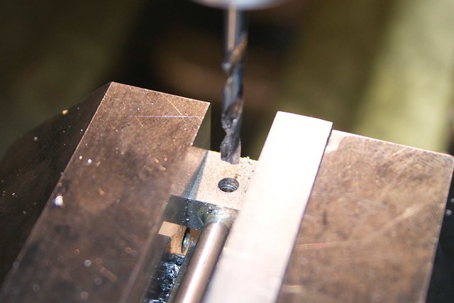
However, when drilling I could feel the drill wandering, because of the inside hole and the harder silver-solder, so the hole was opened out to reaming size with the tiny boring bar:


then reamed.

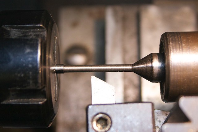
Now I can flip the part around to hold in a collet to turn the outer end down to 1/8" with a center:


before threading the central section 3BA:


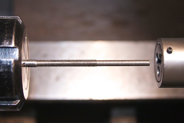
Even though the core diameter of 3BA is a hair over 1/8", the die marked up the 1/8" section which was somewhat annoying, so that had to be smoothed out again. Yet another reason why I should learn to do single-point threading!  :embarassed:

One thing I've found with this 5/32" SS rod is that, despite being "precision ground", it's actually about a thou oversize (I suspect so they can also sell it as 4mm) so I had to take it down with emery paper to fit the glands:


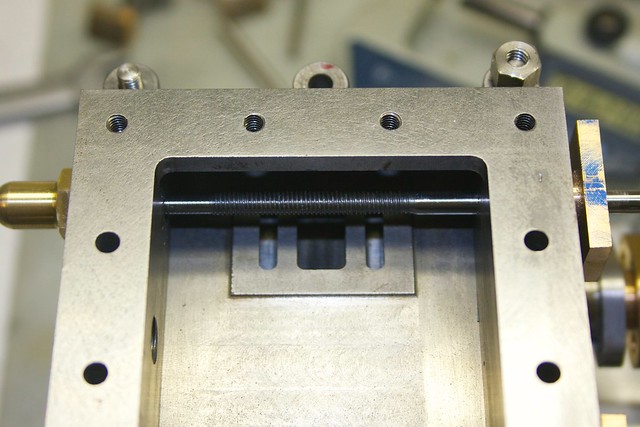
A fit in the steam chest shows that the threads overlap the valve locations correctly  :pinkelephant:


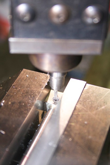
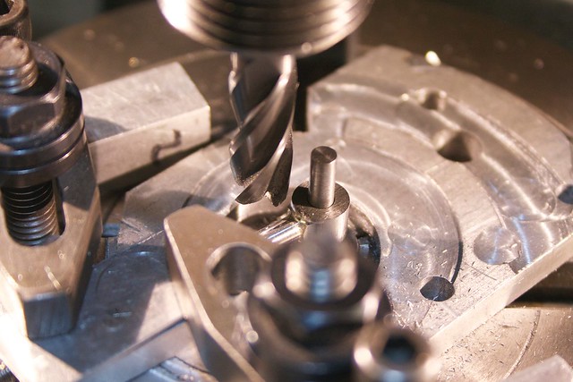
The final operations were rounding the ends on the rotary table:


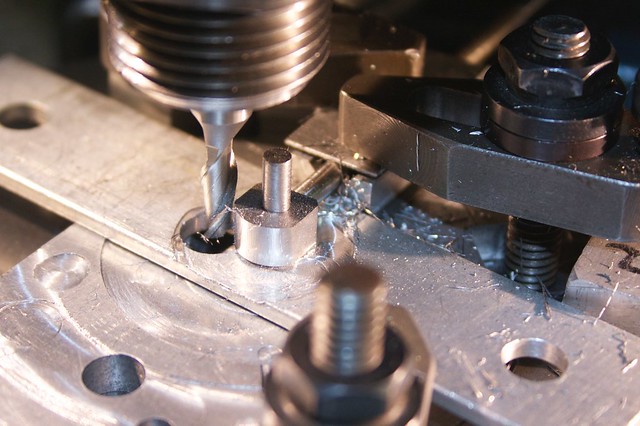
with the radius end mill just skimming the rod for the join radius:


and a bit of filing blended the radii quite nicely:


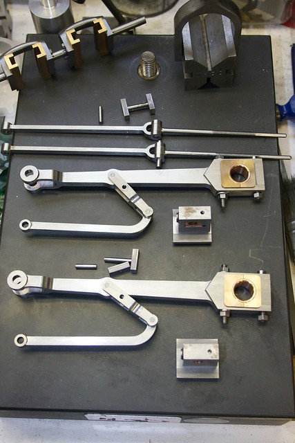
With both done, it's time for a trial assembly  :cartwheel: I've amassed quite a collection of parts!


The crossheads needed a bit of a skim off the bottom to match the piston rod locations after bolting down the cylinder block, and to compute how much, I measure the distance between the top of the piston rod and the top of the crosshead when screwed in:


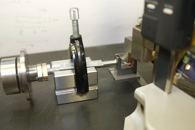
and the same distance after assembly (but not screwed together) with the crosshead in the crosshead slides. This told me I had to skim about 2 thou off one, and 8 thou of the other:


After a bit more fitting work everything goes together (with temporary pins!) and it's starting to look like Muncaster's Joy's Valve Gear Engine! :whoohoo:


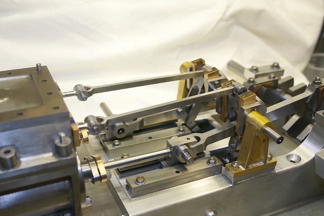
It's a little stiff at one point in the cycle, so I need to figure out where that's coming from. Next will be valves, and the final parts are the flywheel of course, and the handle that controls the valve timing.

Thanks again for following along on this adventure!

Simon

Offline Jo

  • Administrator
  • Full Member
  • *****
  • Posts: 15305
  • Hampshire, england.
Re: Muncaster's Joys Valve Engine
« Reply #393 on: August 05, 2014, 05:57:02 AM »
It is coming together nicely Simon 8)

An alternative idea with those rods popping out during silver soldering is to use a needle file to cut a little short groove down the side of the rod.

Jo
Enjoyment is more important than achievement.

Online Kim

  • Global Moderator
  • Full Member
  • *****
  • Posts: 7925
  • Portland, Oregon, USA
Re: Muncaster's Joys Valve Engine
« Reply #394 on: August 05, 2014, 06:38:43 AM »
A few more parts, amazingly well done Simon!
Your going to have this engine running soon! :)
Kim

Offline fumopuc

  • Full Member
  • *****
  • Posts: 3254
  • Munich, Germany, EU
Re: Muncaster's Joys Valve Engine
« Reply #395 on: August 05, 2014, 06:34:08 PM »
Yes  Simon, I like it.
Kind Regards
Achim

Offline gbritnell

  • Full Member
  • ****
  • Posts: 2472
Re: Muncaster's Joys Valve Engine
« Reply #396 on: August 05, 2014, 06:38:16 PM »
Your usual fine (very fine) work Simon. I can't wait to see the finished engine.
gbritnell
Talent unshared is talent wasted.

Offline Dave Otto

  • Full Member
  • *****
  • Posts: 4707
  • Boise, Idaho USA
    • Photo Bucket
Re: Muncaster's Joys Valve Engine
« Reply #397 on: August 06, 2014, 01:43:48 AM »
Lots of very nice parts there Simon!

Yes, it it is going to be fun to see this one in operation.

Dave

Offline Don1966

  • Full Member
  • *****
  • Posts: 6818
  • Columbia, MS
Re: Muncaster's Joys Valve Engine
« Reply #398 on: August 06, 2014, 02:02:06 AM »
Very nice work Simon and I thoroughly enjoy following along on your built. Those linkage are just to cool and the write up is awesome. I like...................... :praise2:

Don

Offline Bearcar1

  • Full Member
  • ****
  • Posts: 829
  • Chicagoland Area, USA
Re: Muncaster's Joys Valve Engine
« Reply #399 on: August 06, 2014, 02:29:52 AM »
Whewee! NICE job Simon! Thanks for the updates and pictures. Sure is a fine looking beast.


BC1
Jim

Offline Hugh Currin

  • Full Member
  • ****
  • Posts: 720
  • Box Elder, SD, USA
    • www.currin.us
Re: Muncaster's Joys Valve Engine
« Reply #400 on: August 06, 2014, 05:46:56 AM »
Simon:

Very nice parts. Your work is meticulous and inspiring. Thank you for posting the build and in the detail you've included.

I'm curious though. Back when you built the conrods you started with round stock and used a bandsaw to get rectangular parts. I remember this because I thought if I tried this my saw would wander enough to ruin the parts. But on these valve rods you silver soldered square stock to the stainless rods, and then made them round using a rotary table. I thought you could have made the round end and silver soldered it to the ground rod.


Are these choices due to stock on hand or is there more to it?

Again, thanks for posting the build. It's coming together very well.

Hugh
Hugh

Offline arnoldb

  • Administrator
  • Full Member
  • *****
  • Posts: 1341
  • Windhoek, Namibia
Re: Muncaster's Joys Valve Engine
« Reply #401 on: August 06, 2014, 07:03:48 PM »
VERY nice work Simon  :praise2:

I agree with Jo about a file mark or two.  I've also had good results with similar jobs by turning the end that must go into the hole a couple of thou under size, and then knurling it to make it fit fairly tight in the hole.  The knurls provide ventilation, as well as excellent penetration.

Kind regards, Arnold
Building an engine takes Patience, Planning, Preparation and Machining.
Procrastination is nearly the same, but it precludes machining.
Thus, an engine will only be built once the procrastination stops and the machining begins!

Offline smfr

  • Full Member
  • ****
  • Posts: 1203
  • San Francisco Bay Area, California
Re: Muncaster's Joys Valve Engine
« Reply #402 on: August 06, 2014, 11:03:46 PM »
Simon:

Very nice parts. Your work is meticulous and inspiring. Thank you for posting the build and in the detail you've included.

I'm curious though. Back when you built the conrods you started with round stock and used a bandsaw to get rectangular parts. I remember this because I thought if I tried this my saw would wander enough to ruin the parts. But on these valve rods you silver soldered square stock to the stainless rods, and then made them round using a rotary table. I thought you could have made the round end and silver soldered it to the ground rod.

Are these choices due to stock on hand or is there more to it?

Hi Hugh, thanks for the nice comments!

The reason I didn't make the ring first and just solder it on is that I wasn't able to guarantee accuracy that way. For me at least, things always move around during silver soldering, especially since you need a solder gap, so I tend to view silver soldering as a way to build up a bigger lump of metal that will be machined as one piece later.

Of course there are alternatives, building jigs etc to keep things aligned, but then you risk the solder sticking to the jig. At least for this case, my way seemed to turn out OK :)

Simon


Offline Hugh Currin

  • Full Member
  • ****
  • Posts: 720
  • Box Elder, SD, USA
    • www.currin.us
Re: Muncaster's Joys Valve Engine
« Reply #403 on: August 07, 2014, 04:00:27 PM »
Simon:

Thanks. There are always many directions, and most of them can work. I was thinking to assemble as above then finish only the faces and bore after putting them together. I suppose my inclination is to avoid rotary table work when I can.

At least for this case, my way seemed to turn out OK :)

Now that's an understatement. It worked extraordinarily well.

Hugh
Hugh

Offline Roger B

  • Global Moderator
  • Full Member
  • *****
  • Posts: 6164
  • Switzerland
Re: Muncaster's Joys Valve Engine
« Reply #404 on: August 07, 2014, 07:17:06 PM »
Coming along very nicely  :ThumbsUp:  :ThumbsUp: Not long to the video and maybe the happy dance  :)
Best regards

Roger


SimplePortal 2.3.5 © 2008-2012, SimplePortal