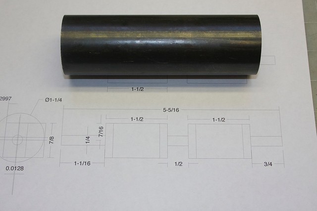
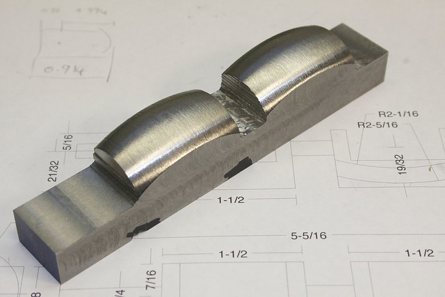
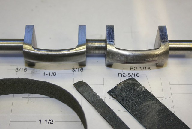
It was finally time to tackle the valve guides (I suppose this part could be described as the trunnions; the guides are actually separate bronze arcs that screw into this part). Just so you know what I'm talking about, here are the plans:

There are some tricky curves here that required a bit of

.
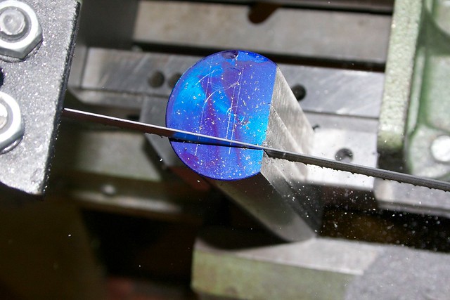
I started with a lump of mystery metal:
This came from the estate sale a model engine machinist and there were two of them, so I suspect it was purchased to make crankshafts. I guessed it would therefore be easy to machine, and that turned out to be correct. After a bit of cutting, I'm pretty sure this is 1144 (Stressproof). Just the ticket!
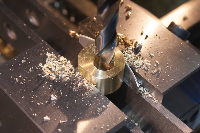
I trimmed it to length in the bandsaw (actually a bit shy of what I needed, so I'll probably end up with some visible center drill holes in the ends; is that bad form for a finished part?
As with the conrods, I cut off the sides in the bandsaw, cutting one side at a time, and machining each after cutting to keep things square:
I've found that I can tap the part to line it up in relation to the blade travel, by having the blade just rub on the vertical surface and tapping until it rubs in the same way all the way down; that way I can get a pretty darn straight cut over the 4.5" length or so. After cutting off three sides, I realized i could probably have started with some flat bar

(not that I have any in stock of the right size).
Some excess material was cut away with a combination of bandsaw and rougher mill:
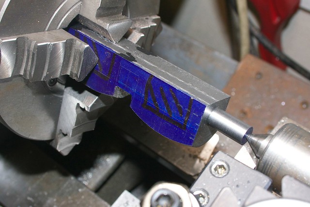
Now things start to get interesting. There are curves on two axes here, so I was thinking of those "hoops" as part of a sphere, whose axis happens to lie a little above the axis of rotation. That prompted a rare excursion for the ball turner to rough out those parts, after locating the part in the 4-jaw chuck. There's a lot of overhang on the ball turner, but I was able to fit a 1-2-3 block and some shims under the cutting head to stiffen it up:
That leaved me with this:
In hindsight this wasn't really necessary; I could have done the rough milling on the rotary table later, but it did make things quicker and it was rewarding to see a partial shape emerging.
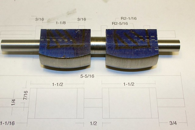
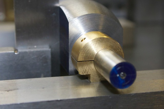
Now the main shaft could be turned down (at this point to 3/8", rather than the final 1/4") which was done in the 4-jaw since accuracy wasn't critical:
which leaves us with this:
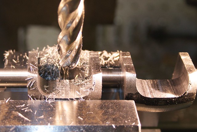
Now I used the rougher to get rid of the bulk of the material between the "webs":
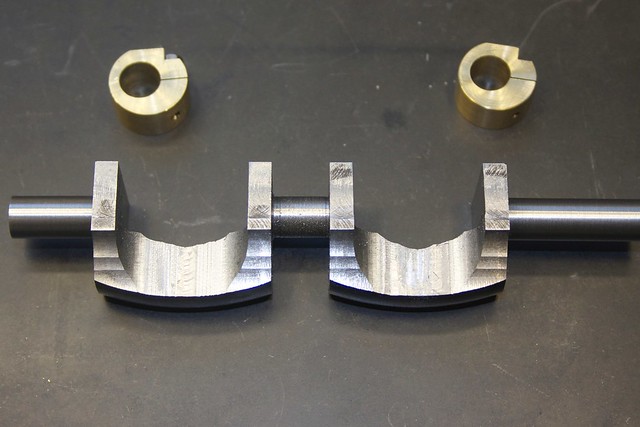
Remember I said that the "hoops" form part of a sphere with its axis above the axis of the shaft? To help with shaping these on the rotary table later, I made a couple of eccentric collars which can be clamped down on the shaft:
making sure I had a flat on each so they could be lined up with each other, and the part:
You'll see those in use later.
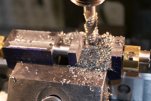
The bulk of the shaping was done on the rotary table, so I needed a fixture plate to locate everything, and provide enough clamping room for a couple of V-blocks etc. A bit of Al plate was cleaned up with the face mill:
(interesting patterns there from unsupported center of the plate ringing as it was cut). This plate has holes for setting up to cut both sides of the part, so two locating holes which will be held at the center of the rotary table with my usual pin arrangement (2" apart matching the inter-cylinder distance of the engine), some holes for clamping to the rotary table at each position, and milled recesses to accurately hold two V-blocks at the appropriate places. Various other threaded holes accept hold-down studs, threaded under power with this handy spiral tap:
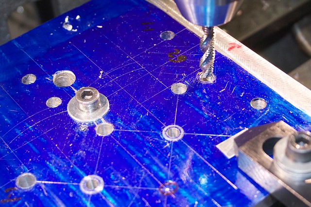
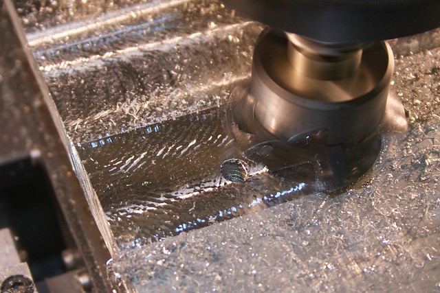
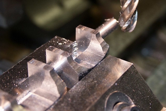
Before setting up the rotary table, I took off as much material from the part as I dared with a big ball-end mill:
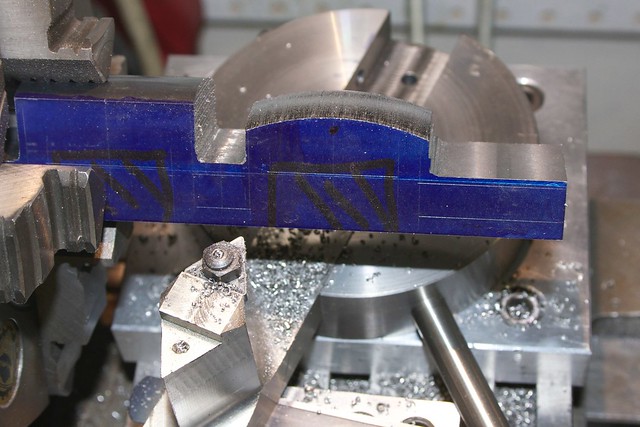
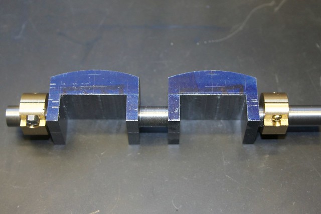
Now down to business. The rotary table is set up, and the plate located on the pin for the rear webs in this photo:
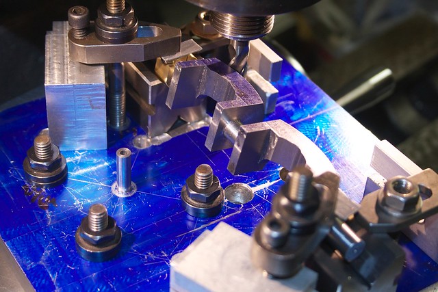
You can see the V-blocks in their recesses; the back one is pushed back a little to give some tool clearance, but the closer one is in the right spot, and of the webs pushed against it to locate the part. Now with this arrangement, I can take some reasonably heavy cuts by side milling to get the outer radius closer to final size:
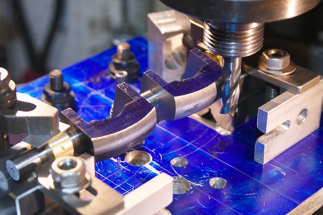
After each cut, I rotate the part in the V-blocks, which is where those eccentric collars come into play; they make sure the axis of rotation here is correct for the hoops. Here you can see I've done one side, then moved the plate for the second side and taken a few cuts:
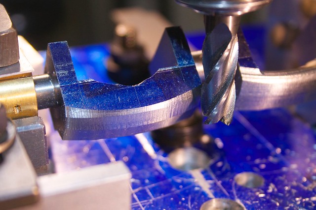
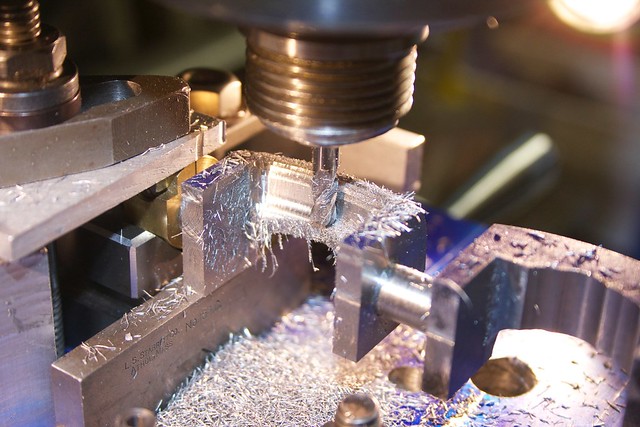
After those roughing cuts I used a 3/16" ball-end mill for the final shaping:
At this stage I just clamped the part with no rotation, and used a spreadsheet I generated from my drawing to step off the cuts. I could go all the way across the outside, then worked my way over the top and cut the inside surface between the webs:
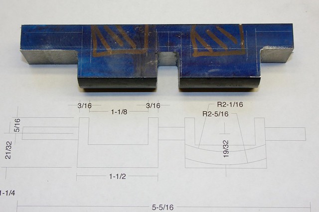
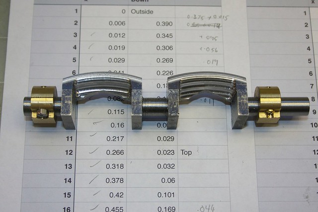
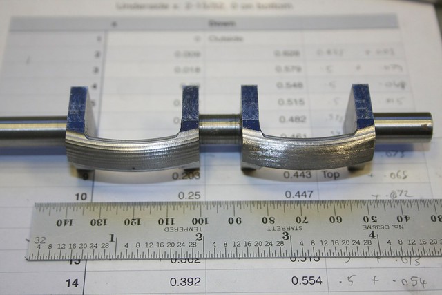
Progress so far (on top of the step-off chart):
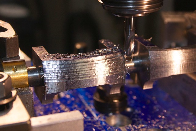
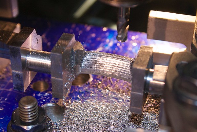
The part was then turned over, and a second set of step-off numbers used to shape the underside:
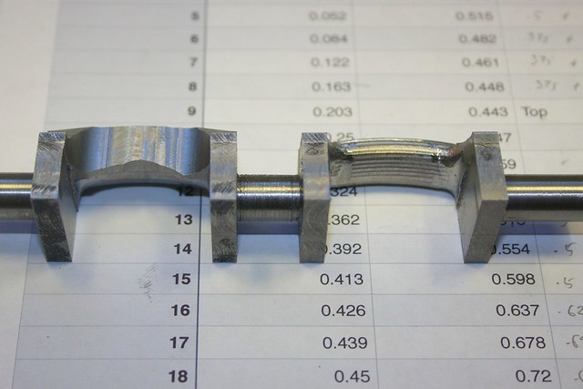
One side done, one to go:
Now we can start filing! Here I've just started one one side:
I've learned with filing not to be too timid! You have to start with a nice coarse file to get rid of the machining marks and do any additional shaping, and only then move onto the finer files, largely just to remove the marks from the file before. After working my way down to Swiss files, I used some strips of wet & dry to remove the filing marks:
Inevitably you have to go back to files and clean up some spots, and in some cases you can't really see the final shape until the surface has some shine to it.
There's one thing left to do before I start the final machining on this part! Cutting away so much material made it go a bit banana-shaped (seems to happen even with stressproof steel), so I needed to persuade things back into alignment. I tried bending it cold in the vise, but it wouldn't take. So I drilled a 3/8" hole in a bit of bar to act as a handle, put the part in the 3-jaw, and applied the propane torch. I did one web first, with an indicator on the central section of shaft, then when that was close, did the other web (otherwise one web would have likely bent more than the other).

When it was hot a bit of pressure on the end of the bar could actually get the bend to stick. After getting it within about 0.08" runout I flipped it around and corrected from the other end. I still have 1/8" to take off the shaft, so I have plenty of wiggle room.
So, a final polish after the heating, and I'm left with this:
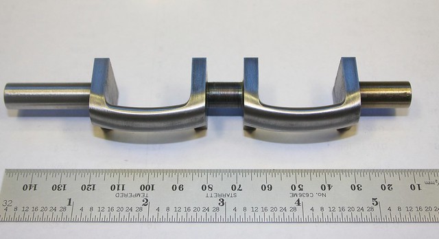
Next will be taking the shaft down to 1/4" between centers.
Congratulations if you made it through this never-ending post, and thanks for following along!

Simon


