Author Topic: Muncaster's Joys Valve Engine  (Read 159785 times)

Offline cfellows

  • Rest In Peace
  • Full Member
  • *
  • Posts: 1700
Re: Muncaster's Joys Valve Engine
« Reply #270 on: April 06, 2014, 06:19:55 PM »
Nice job on the crankshaft, Simon.  I also prefer the Loctite solution over silver soldering, particularly with crankshafts.  I use Loctite 620.  Amazing how fast that stuff sets up, sometimes before I'm actually finished with assembly.   :Doh:

Silver soldering seems to require a sweet spot in the heat range to get a good joint.  Either too hot or not hot enough and the solder won't flow into the joint, just beads up and runs off.  I also worry about the heat warping the crankshaft.

Chuck
So many projects, so little time...

Offline Roger B

  • Global Moderator
  • Full Member
  • *****
  • Posts: 6164
  • Switzerland
Re: Muncaster's Joys Valve Engine
« Reply #271 on: April 06, 2014, 06:31:23 PM »
Looks like you are working your way through this one  :ThumbsUp: :ThumbsUp:   
Best regards

Roger

Offline kvom

  • Full Member
  • *****
  • Posts: 2649
Re: Muncaster's Joys Valve Engine
« Reply #272 on: April 06, 2014, 06:38:58 PM »
620 does set up fast, and the larger the contact area the faster.  When quartering the drivers on my locomotive I had to practice sliding on the wheels in one smooth motion without disturbing the setup.  Crankshaft quartering is a bit less challenging.  I have a set of .001" over/under reamers that I generally use for sliding/press fits.

620 is for sliding rather than press fits.  FWIW, when I had to remove a pair of drivers to remake an axle, I had to heat the joints with a torch to 500 degrees and then press it out.  Even with a 20-ton press after heating the joints let go with quite a bang.

Offline zeeprogrammer

  • Full Member
  • *****
  • Posts: 6811
  • West Chester, PA, USA
Re: Muncaster's Joys Valve Engine
« Reply #273 on: April 06, 2014, 07:37:55 PM »
What end of the pin did you mill down? Just the one opposite the end you peened? Or both? (Cause I'm wondering why you peened.)

Zee, the peening is really just to get the pin to fill the hole, so that the join becomes almost invisible after cleanup. I peened both ends, and milled off and filed both ends, so the pins just disappear. (I rather liked the look with the pins visible though!).


Ah! I'm glad I asked!!!
Carl (aka Zee) Will sometimes respond to 'hey' but never 'hey you'.
"To work. To work."
Zee-Another Thread Trasher.

Offline Jasonb

  • Full Member
  • *****
  • Posts: 9489
  • Surrey, UK
Re: Muncaster's Joys Valve Engine
« Reply #274 on: April 06, 2014, 07:42:51 PM »
I'd save the $100 on the thermometer and put it towards a bigger burner. You want something with a 25-28mm dia nozzel and a decent Propane bottle at least 3.9kg preferably more like 7kg and a 4bar regulator. Or whatever your equivalents are.

Also worth getting some flux that is designed to stay good during prolonged heating, its a bit harder to remove but worth having for any large items that take a bit longer to get upto temperature.

I was forgetting its a double high not a compound. The load is not so much from running it fast but the torque that can be generated when the engine starts or if put under load at lower speeds.

J

Offline smfr

  • Full Member
  • ****
  • Posts: 1203
  • San Francisco Bay Area, California
Re: Muncaster's Joys Valve Engine
« Reply #275 on: April 07, 2014, 04:24:59 AM »
This morning it was time to get the crankshaft ship-shape! I carefully set up in the band saw, ordering the cuts so that the bit of rod being cut was the same bit clamped in the vise (thus avoiding undue forces on the glued and pinned joints):


That meant inside followed by outside cut on one side, flip the part around and repeat. There's a parallel to prevent the part from rotating under the force of cut, and some shims under the ends of the webs for support. Of course I was very careful to prevent the saw from dropping down and cutting the journals.

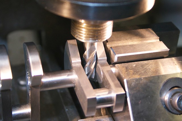
The saw cuts could then be cleaned up by milling, again following the "clamp the part you're cutting" rule:


The inner webs require something a bit more fiddly to hold them. As part of the great silver-soldering fiasco, I had made the fixture you see here to hold the parts for soldering (but never used it):


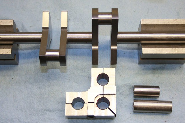
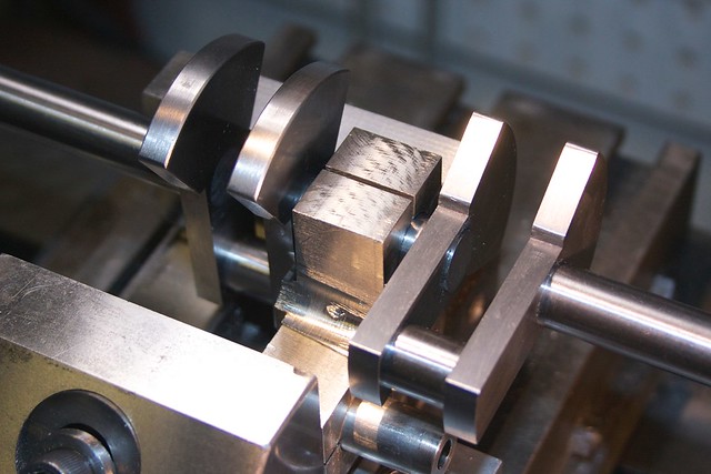
but I finally found a use for it to hold the inner bit of the main shaft for cleaning up these ends:


A quick note on how I mill up to a flat surface like this. I have a poor man's DRO (an old indicator clamped between the carriange and a carriage-stop):


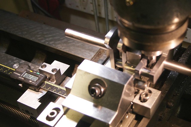
I'll position the tool for the cut, and then crank the dials until the tool just touches part of the finished surface, then zero the indicator. With an end mill, it's good to rotate the spindle a partial turn and do this a few times, since different parts of the tool will touch. If you suspect the part isn't perfectly lined up, do this on both sides of the cut and take the one with least depth of cut.

Now touch the tool on the bit to be milled away, and note the indicator reading; this is of course how much to remove. Now you can start making cutting passes, being pretty confident that as you get close to zero, you're approaching the finished surface. For these cuts I had about 0.025" to remove and did passes of about 0.004".

With this technique you should be able to get within 0.0005", with the remainder easy to clean up with a file. Here's a cut up to the finished surface, and it shows that either my vise is out of tram, or (more likely) the web isn't quite square:


The four milled surfaces were then cleaned up by draw filing, and given a bit of emery-on-a-stick.

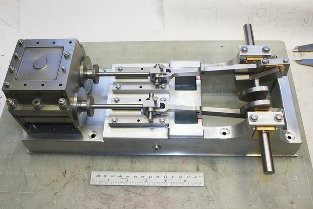
Now we're at an exciting point of first assembly  :whoohoo: I washed some parts, found a couple of bits of 1/4" rod to put in the crossheads, and put everything together. One of the bearings needed a bit of fitting to go between the webs on one side, but apart from that everything fit and turns over fairly smoothly  :pinkelephant:


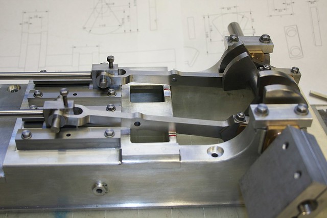
Turning it over found a bit of interference between the conrods and the base, which was quickly relieved with a bit of filing (will be nicely profiled later):


and the slides will need a bit more fitting before I can tighten them down. But, hey, this is finally starting to look like something:


I think I'll do the cylinder covers next, and then I'll be building up the valve linkage parts from the bottom up. That should be fun!

Simon

Online fumopuc

  • Full Member
  • *****
  • Posts: 3253
  • Munich, Germany, EU
Re: Muncaster's Joys Valve Engine
« Reply #276 on: April 07, 2014, 05:55:05 AM »
Hi Simon, great job. I like your crankshaft.
Kind Regards
Achim

Online Kim

  • Global Moderator
  • Full Member
  • *****
  • Posts: 7922
  • Portland, Oregon, USA
Re: Muncaster's Joys Valve Engine
« Reply #277 on: April 07, 2014, 06:02:47 AM »
Great work on the crankshaft Simon!  It looks wonderful!

And I'd forgotten how big your engine was! Wow! :o

Just curious, did you loose any  alignment when you cut the main shaft?  I did the same process on my Marine Twin and believe things snapped out of alignment by a few thousandths when I did this. That was fine for my tolerances though :). Wondering about your experience on this point.

I'm excited to see the linkages come together. Thats really going to make  this engine!
Kim

Offline smfr

  • Full Member
  • ****
  • Posts: 1203
  • San Francisco Bay Area, California
Re: Muncaster's Joys Valve Engine
« Reply #278 on: April 07, 2014, 06:13:38 AM »
Great work on the crankshaft Simon!  It looks wonderful!

And I'd forgotten how big your engine was! Wow! :o

Thanks Kim! Yeah, it's not small :)

Just curious, did you loose any  alignment when you cut the main shaft?  I did the same process on my Marine Twin and believe things snapped out of alignment by a few thousandths when I did this. That was fine for my tolerances though :). Wondering about your experience on this point.

I didn't get a large amount of spring; I put one end in a collet and got about 2-3 thou of runout at the other end, but that was easy to push around with a bit of finger pressure. The crankshaft seems to run in the bearings quite happily.

Simon

Online Jo

  • Administrator
  • Full Member
  • *****
  • Posts: 15305
  • Hampshire, england.
Re: Muncaster's Joys Valve Engine
« Reply #279 on: April 07, 2014, 07:50:51 AM »
It's beginning to look really impressive  :popcorn:

Jo
Enjoyment is more important than achievement.

Offline peatoluser

  • Full Member
  • ****
  • Posts: 242
  • liverpool UK
Re: Muncaster's Joys Valve Engine
« Reply #280 on: April 07, 2014, 11:28:07 AM »
Yes it certainly is. I'm glad you found a use for the soldering fixture. following along with interest

peter

Offline Don1966

  • Full Member
  • *****
  • Posts: 6818
  • Columbia, MS
Re: Muncaster's Joys Valve Engine
« Reply #281 on: April 07, 2014, 11:56:51 AM »
That's looking awesome Simon and nice job on the crank even with the failure of the other. I like ......... :praise2:

Don

Offline b.lindsey

  • Global Moderator
  • Full Member
  • *****
  • Posts: 13860
  • Dallas, NC, USA
    • Workbench-Miniatures
Re: Muncaster's Joys Valve Engine
« Reply #282 on: April 07, 2014, 12:28:51 PM »
Simon, I hadn't checked in on this one in a while, but I must say its a most impressive build and the finishes are just superb. I'll definitely be checking in more often and looking forward to seeing this one run!!

Bill

Offline kvom

  • Full Member
  • *****
  • Posts: 2649
Re: Muncaster's Joys Valve Engine
« Reply #283 on: April 07, 2014, 12:57:38 PM »
 :ThumbsUp: :ThumbsUp: :ThumbsUp:

Offline NickG

  • Global Moderator
  • Full Member
  • *****
  • Posts: 1430
Re: Muncaster's Joys Valve Engine
« Reply #284 on: April 07, 2014, 01:51:01 PM »
Yeah it does look brilliant. Crank came out really good, I was wondering about the loctite too as realised mine is a anaerobic too hence why it didn't set last time I tried! I bet lot of people make the mistake you avoided by not clamping the same bit as you're cutting out too!


SimplePortal 2.3.5 © 2008-2012, SimplePortal