Author Topic: Muncaster's Joys Valve Engine  (Read 159886 times)

Offline Don1966

  • Full Member
  • *****
  • Posts: 6818
  • Columbia, MS
Re: Muncaster's Joys Valve Engine
« Reply #210 on: February 09, 2014, 02:40:13 PM »
Nicely done Simon and I know it was a lot of work to get that part done.


Don

Offline smfr

  • Full Member
  • ****
  • Posts: 1203
  • San Francisco Bay Area, California
Re: Muncaster's Joys Valve Engine
« Reply #211 on: February 09, 2014, 04:57:02 PM »
Looks good Simon, what size thread is that on the rods? looks a bit light for a large engine

Jason, the thread is 3BA. I agree it's a bit small; the weak point is definitely the undercut at the end of the threads. I think you've convinced me that I need to silver-solder the rods in (assuming I can get solder to stick to 303 SS and 1144!) :)

However I won't do the soldering until I've got bearings done to get the length right. That way I can still hold the piston rod in a collet to finish the piston end.

Simon

Online Kim

  • Global Moderator
  • Full Member
  • *****
  • Posts: 7929
  • Portland, Oregon, USA
Re: Muncaster's Joys Valve Engine
« Reply #212 on: February 09, 2014, 05:01:17 PM »
That looks great Simon!  You're really getting along there!

Speaking of sharp edges, is that a dab of your blood I see on the inside of the back cross head?  :o Or just red layout dye? I could mail you a pirate band-aid!  :Lol:

Excellent work Simon, thanks for taking the time to share it with us!
Kim

Offline smfr

  • Full Member
  • ****
  • Posts: 1203
  • San Francisco Bay Area, California
Re: Muncaster's Joys Valve Engine
« Reply #213 on: February 09, 2014, 05:16:16 PM »
That looks great Simon!  You're really getting along there!

Speaking of sharp edges, is that a dab of your blood I see on the inside of the back cross head?  :o Or just red layout dye? I could mail you a pirate band-aid!  :Lol:

Thanks Kim! Don't worry, that's just some red Sharpie I was using to mark the crosshead  :D

Simon

Offline Jasonb

  • Full Member
  • *****
  • Posts: 9491
  • Surrey, UK
Re: Muncaster's Joys Valve Engine
« Reply #214 on: February 09, 2014, 06:01:22 PM »
You may need to use a different flux, overhere Tenacity 5 or HT5 are needed for stainless as they remove the chrome oxide

Offline smfr

  • Full Member
  • ****
  • Posts: 1203
  • San Francisco Bay Area, California
Re: Muncaster's Joys Valve Engine
« Reply #215 on: February 10, 2014, 06:15:58 AM »
You may need to use a different flux, overhere Tenacity 5 or HT5 are needed for stainless as they remove the chrome oxide

Right, I think I want the Harris "Black" flux, which of course I failed to include when I ordered my silver soldering supplies  :killcomputer:

A little more progress today, making the stop block thingies that hold the bearings in the conrods (no idea what their real name is!). Two bits of 1144 were milled close to size, then carefully set up in the vise for drilling and reaming 3/16":


I was careful here because I only have a few thousands to spare on the sides, and I wanted these to match the conrod widths. I peck-drilled to reduce the chances of the drill wandering.

With a bit of fussing they fit nicely. The top one has had the draw-file treatment:


It's all sharp edges at the moment. I'm not sure if I should chamfer all my edges, or just very slightly ease them with a file so they don't feel sharp.

The blocks are held in by pins. After trying to tighten one and have the head spin around, I realised that they should probably have a square section under the head, and fit into a square hole in the conrod; the round head is true to the plans.


I managed to get them tightened up for the filing, though, so I'll modify them later if necessary.

You can also see that I started preparing material for the bearings  :cartwheel:

Simon

Offline ths

  • Full Member
  • ****
  • Posts: 1801
  • Kangaroo Valley, NSW, Australia
Re: Muncaster's Joys Valve Engine
« Reply #216 on: February 10, 2014, 10:43:19 AM »
A slight relief of the edges would be truer to prototype (if there was one!), and would make it look less machined, despite all your painstaking hand work.

Cheers, Hugh.

Offline fumopuc

  • Full Member
  • *****
  • Posts: 3256
  • Munich, Germany, EU
Re: Muncaster's Joys Valve Engine
« Reply #217 on: February 10, 2014, 07:52:14 PM »
Hi Simon, you have again some perfect jobs done. It looks really very good. If you don't want to solder your rods, I am sure some Loctite  or epoxy glue will bring  you on the safe side of this case.
Kind Regards
Achim

Offline NickG

  • Global Moderator
  • Full Member
  • *****
  • Posts: 1430
Re: Muncaster's Joys Valve Engine
« Reply #218 on: February 10, 2014, 09:44:55 PM »
Yeah epoxy would prob be a good choice. Very simple calc to see what the max likely stress is though if you know the max pressure you will use - might be worth doing.

Offline smfr

  • Full Member
  • ****
  • Posts: 1203
  • San Francisco Bay Area, California
Re: Muncaster's Joys Valve Engine
« Reply #219 on: February 16, 2014, 07:09:23 AM »
After some time in the garden this morning (things are finally growing after getting some rain here in California), I had a mostly productive afternoon and evening in the workshop (aka garage).

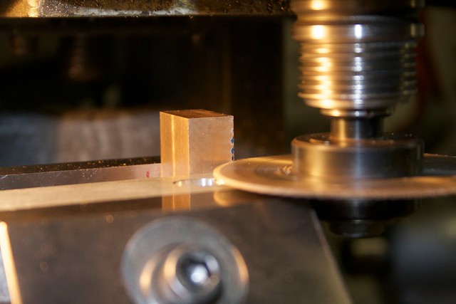
Both the conrods and the crossheads need bearings, so I planned to work on both at once to reduce the number of setup changes. Some bits of my precious Bunting bronze were bandsawed off and milled square, trying to fit the bearings into the minimum amount of raw material. When close to final size I used a thin slitting saw to cut the bearings in two, again trying to save material:


The end result was four pairs of bearing parts (two for the crossheads, two for the conrods). I then soldered the pairs together using electrical solder, but this time I remebered to put some punch marks on the mating faces, and use a bit of soldering flux. A bit of solder wire was laid over the joint, then the part carefully heated on the sides with a propate torch on low, to get the parts to melting temperature rather than blasting the solder directly.


Pretty soon the solder melted and wicked into the joint  :ThumbsUp:

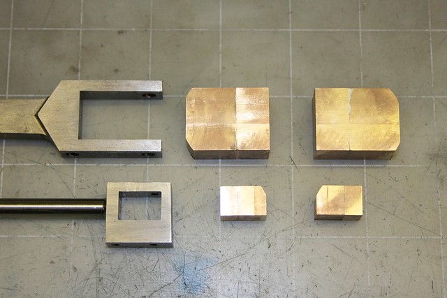
Four of those, and we have our bearings in the raw:


I should say a bit about the order of operations here. I'm not sure if this is the usual procedure, but it makes sense to me. For each bearing:
  • Square up the material for each half of the bearing, leaving things a bit oversized. You want to aim for the solder join to be on the centerline of the final hole.
  • Put a few punch marks on the mating faces to leave a solder gap, then apply flux, and solder as described above. Leave to cool. [Edit: or sweat the parts together by tinning mating surfaces, matching them up, then heating again to melt the solder].
  • Inevitably the soldering leaves the two halves slightly misaligned. You can mill them square again at this point, and take closer to final size. Take care that the solder joint ends close to where the hole center will be.
  • Then fit to the part (more about that below).
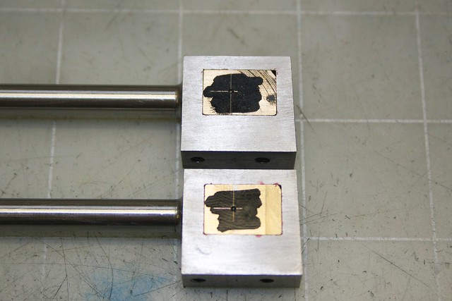
It was at this point, while comparing the conrod bearings with the bearing slot, that something looked a bit fishy  :thinking: Going back to the CAD model I see that I've made a mistake on the conrod, and taken the slot too deep  :hammerbash: However I think I can cover the boo-boo by making the bearing flanges a little wider, but I'll end up with non-square bearings.

Anyway, the conrod bearings were put to one side to focus on the crosshead bearings. First, we make sure everything is numbered so we know where things go on reassembly:


Then comes the tedious process of getting a close fit of the bearings in their slot. This consisted of milling small amounts off the bearings, lots of rubbing on files, and filing the slots with the help of the red Sharpie. I did find that my previous filing with the guides was still pretty skewed, requiring some squaring up with a 1/8" end mill:


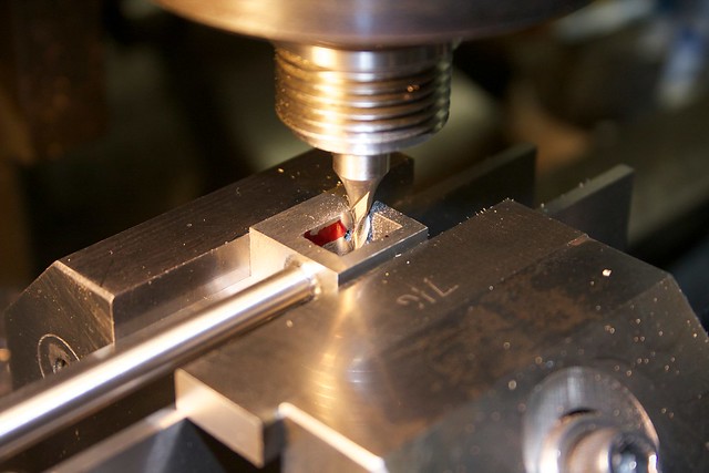
I have a second-hand square-section file that has had a face ground down by the previous owner, which turned out to give a very handy safe edge for squaring up the corners of the slot. The Sharpie is also useful to see where things are rubbing as the bearing is test-fitted.

This took about 1-1.5 hours per bearing; here's the first one done:


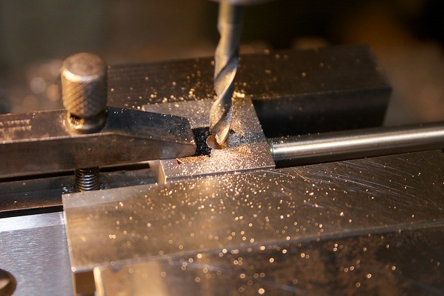
And the second (or so I thought!), marked up for hole-drilling. I'm drilling them in situ, so the hole is square to the part:


A machinist's clamp holds the bearing in place for drilling:


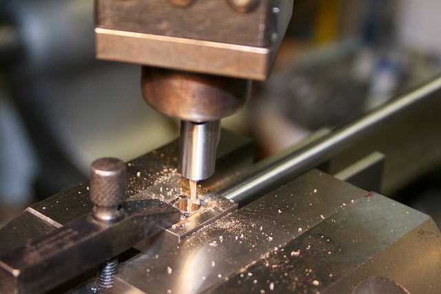
Close to pre-reaming size I did a pass with a small boring bit to make sure the hole was square:


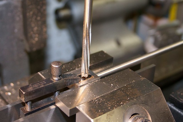
then reamed with a spiral flute reamer (a straight-flute reamer might have problems with the solder joint):


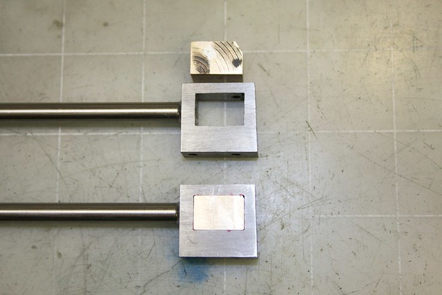
However, when drilling the second bearing I noticed the machinists clamp wobbling around, and found that the whole bearing was too loose. I'd taken too much off by milling, and holding it up to the light showed the poor fit:


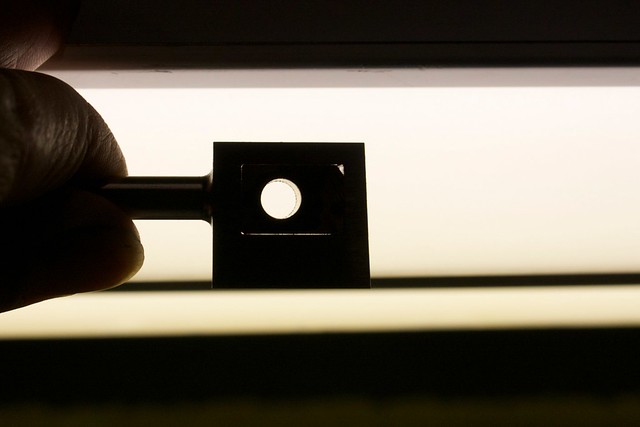
You can see in the second photo how it's only touching in the lower corners. That's bad, because when the bearing is separated, the two halves are going to be really loose, and will probably go askew since they aren't bearing on flat surfaces.

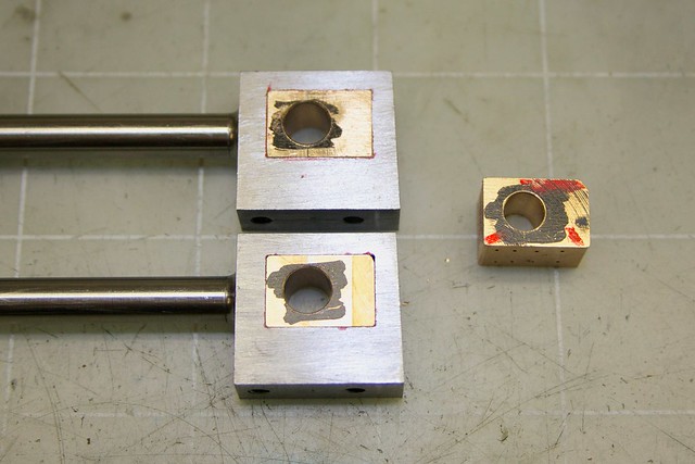
So I remade that bearing, squeezing just enough material out of a couple of bits of bronze scrap from the same stock. The second time the fit was really snug. So, both done, and the reject:


I left the bearings a little over thickness; I plan to put them on a mandrel and take down the surfaces to leave a slight raised hub, so that the forks of the conrod clear the crosshead and bearing body, and just fit the hub. The forks will need a bit of fitting work too.

These bearings will be split, and shaped for the wedge later; at least I can use them in their current form for test-fitting on the engine  :cartwheel:

That's it for today! Thanks for watching, and with any luck I'll have some progress on the conrod bearings tomorrow.

Simon
« Last Edit: February 16, 2014, 05:41:40 PM by smfr »

Offline fumopuc

  • Full Member
  • *****
  • Posts: 3256
  • Munich, Germany, EU
Re: Muncaster's Joys Valve Engine
« Reply #220 on: February 16, 2014, 08:16:36 AM »
Always following along.
Kind Regards
Achim

Offline Jasonb

  • Full Member
  • *****
  • Posts: 9491
  • Surrey, UK
Re: Muncaster's Joys Valve Engine
« Reply #221 on: February 16, 2014, 08:26:53 AM »
Simon I was always tought when soldering part slike this to tin both faces first, that is apply a thin layer of solder, wiping off any excess while still hot. You then put the two together with a littel flux and heat to "sweat" the joint together. This tends to give a closer joint with less solder and as you can see the two surfaces you are sure they are fully coated with solder

J

Offline Jo

  • Administrator
  • Full Member
  • *****
  • Posts: 15305
  • Hampshire, england.
Re: Muncaster's Joys Valve Engine
« Reply #222 on: February 16, 2014, 08:31:18 AM »
Soft solder paste does it even easier  ;)

Jo
Enjoyment is more important than achievement.

Offline zeeprogrammer

  • Full Member
  • *****
  • Posts: 6811
  • West Chester, PA, USA
Re: Muncaster's Joys Valve Engine
« Reply #223 on: February 16, 2014, 01:25:48 PM »
Following along Simon. I always enjoy your posts.

Are you in that part of CA with the drought issues? I hope relief is not far off.

You mentioned the spiral reamer might do better than a straight reamer because of the solder.
I've not come across a spiral reamer. Does it help move shavings out of the way?
Are there other cases where a spiral reamer would be preferred? Or rather...what are the advantages?

Thanks
Carl (aka Zee) Will sometimes respond to 'hey' but never 'hey you'.
"To work. To work."
Zee-Another Thread Trasher.

Offline Doc

  • Full Member
  • ****
  • Posts: 868
  • USA ND
Re: Muncaster's Joys Valve Engine
« Reply #224 on: February 16, 2014, 02:36:42 PM »
 Just caught up on your build and I must say you have done some beautiful work!
And very nice documentation I love it wish I could take nice pictures like that! This has been really nice build and have picked up some nice techniques keep up the nice work!


SimplePortal 2.3.5 © 2008-2012, SimplePortal