Author Topic: Muncaster's Joys Valve Engine  (Read 160097 times)

Offline smfr

  • Full Member
  • ****
  • Posts: 1203
  • San Francisco Bay Area, California
Re: Muncaster's Joys Valve Engine
« Reply #165 on: January 18, 2014, 07:12:13 AM »
A bit more progress here. I drilled and tapped the cylinder block for studs, first the six studs that hold down the valve chest:


A 1-2-3 block bolted down on two sides  allowed for repeatable positioning in case I had to remove the valve chest mid-drilling.

For the valve cover holes, I first drilled and tapped on opposite corners for the valve cover. You can't see it here, but I always start the taps with the tap held in a drill chuck on the mill/drill. If I remove a belt, I can easily rotate the spindle by hand and the return spring is soft enough to just let the tap pull the quill down. After getting the tap started, I release it from the chuck and continue with a tap wrench:


With the valve cover bolted down on two corners, I then freehand drilled the remaining holes, tapping size first, using a punch mark to start the holes in the right place:


While doing this I was thinking about the relative accuracies of this method vs. finding hole locations using a DRO. One limitation of using punch marks to start drilling is that part has to be light enough to slide around to center under the drill point.

Four of the studs are long, and go down through the valve chest into the cylinder block. Here I'm using the pre-drilled holes in the valve cover and chest to continue down into the cylinder block (all the holes are still tapping size at this point—this sequence required a bit of thought to make sure I didn't clearance-drill too soon  :headscratch:):


And the cylinder block is tapped, again letting the part just locate under the tap of its own accord (the vise isn't clamped down):


As always, tapped holes require some touch-up with a file to take off burrs. It's interesting that this happens even in cast iron:


And I made some studs! 6 3BA for the valve chest, 4 long 4BA ones and 2 short 4BA ones done, and 6 more short 4BA ones to go! I used 303 stainless, which would probably get me arrested by the authenticity police, but was much easier to machine than the drill rod I started with since the diameter had to be turned down for the entire length of each stud  :Doh:


I also spent some quality time with wet & dry on the glass plate trying to get rid of the tooling marks on the valve cover. Boy what an effort!

One thing that's slightly worrisome is that four of the stud holes go through to the valve chamber; I'm pretty sure there isn't enough thickness to do a blind tapped hole there in the drawings. So might I be dealing with some steam leaks around those studs?

Simon

Offline Jasonb

  • Full Member
  • *****
  • Posts: 9493
  • Surrey, UK
Re: Muncaster's Joys Valve Engine
« Reply #166 on: January 18, 2014, 07:48:50 AM »
Simon you can avoid the burrs either by spotting through with the clearance drill and making a shallow hole in the part maybe just one turn of thread depth. Or use spotting drills if not locating from another part and drill so the "spot" is just over the thread dia, this in effect puts a small CSK on the hole before tapping and is what I usually do as now I have the DRO I don't spot from another part very often.


Some liquid gasket around the studs will hopefully stop any leaks.

J
« Last Edit: January 18, 2014, 07:54:47 AM by Jasonb »

Offline fumopuc

  • Full Member
  • *****
  • Posts: 3261
  • Munich, Germany, EU
Re: Muncaster's Joys Valve Engine
« Reply #167 on: January 18, 2014, 08:05:56 AM »
Hi Simon, that looks very good. I am still following.
Kind Regards
Achim

Offline steamer

  • Global Moderator
  • Full Member
  • *****
  • Posts: 12699
  • Central Massachusetts, USA
Re: Muncaster's Joys Valve Engine
« Reply #168 on: January 18, 2014, 12:14:34 PM »
That's really nicely done Simon, did you make that tap wrench?....I like it. :ThumbsUp:

Dave

"Mister M'Andrew, don't you think steam spoils romance at sea?"
Damned ijjit!

Offline zeeprogrammer

  • Full Member
  • *****
  • Posts: 6811
  • West Chester, PA, USA
Re: Muncaster's Joys Valve Engine
« Reply #169 on: January 18, 2014, 01:52:27 PM »
I hadn't been around for a while and was wondering what you were up to.
Just finished reading your thread. Always enjoyable and educational.
Fascinating engine and excellent quality.
Carl (aka Zee) Will sometimes respond to 'hey' but never 'hey you'.
"To work. To work."
Zee-Another Thread Trasher.

Offline Don1966

  • Full Member
  • *****
  • Posts: 6818
  • Columbia, MS
Re: Muncaster's Joys Valve Engine
« Reply #170 on: January 18, 2014, 03:00:17 PM »
Awesome Simon, excellent work and an A+ on the JB weld. She's going to be a beaut bud.

Don

Offline smfr

  • Full Member
  • ****
  • Posts: 1203
  • San Francisco Bay Area, California
Re: Muncaster's Joys Valve Engine
« Reply #171 on: January 18, 2014, 06:52:22 PM »
Thanks all, and good to have you back, Zee!

Jason, good tip on the hole counter-sinking. I usually run a small countersink in the hole by hand, but I shall add a step to my drilling/tapping routine  :ThumbsUp:

Dave, the tap wrench came with a set of BA taps and dies from Tap & Die. Handy, but it's a bit fussy to tighten and loosen.

Simon

Offline Tennessee Whiskey

  • Full Member
  • *****
  • Posts: 3781
  • Springfield, Tennessee. USA
Re: Muncaster's Joys Valve Engine
« Reply #172 on: January 18, 2014, 07:04:48 PM »
Simon, I've been quietly following along. Very nice fab work on the bosses :ThumbsUp:and I think even Jo would approve of your studding abilities. I've got to get some kind of reference for these BA sizes, so I'll know how big y'all are talking about. Keep up the good work mate :cheers:

Whiskey

Offline Jasonb

  • Full Member
  • *****
  • Posts: 9493
  • Surrey, UK
Re: Muncaster's Joys Valve Engine
« Reply #173 on: January 18, 2014, 07:40:18 PM »
This is what I made up to know what you are all talking about ;)

Offline Tennessee Whiskey

  • Full Member
  • *****
  • Posts: 3781
  • Springfield, Tennessee. USA
Re: Muncaster's Joys Valve Engine
« Reply #174 on: January 18, 2014, 07:47:20 PM »
Jason, old boy, thanks. I'll copy, paste, and print. You are turning into my "across the pond hero" :cheers:

Whiskey

Offline smfr

  • Full Member
  • ****
  • Posts: 1203
  • San Francisco Bay Area, California
Re: Muncaster's Joys Valve Engine
« Reply #175 on: January 18, 2014, 08:03:29 PM »
Thanks Whiskey  :cheers:

I'm currently having fun hogging out the conrods. It's the kind of stuff that keeps you awake at night  :insane:

Simon

Offline smfr

  • Full Member
  • ****
  • Posts: 1203
  • San Francisco Bay Area, California
Re: Muncaster's Joys Valve Engine
« Reply #176 on: January 26, 2014, 05:27:00 AM »
I've been quiet here for a couple of weekends because...conrods!


Quite a bit of work in those. Apologies for the bandwidth-constrained, this is going to be a picture-heavy post (even more so than usual!).

These started life as a bit of 2" 1144 ("stressproof"), which happened to be in the firesale at SpeedyMetals (and somehow I managed to add 2 sticks to my card  ;D
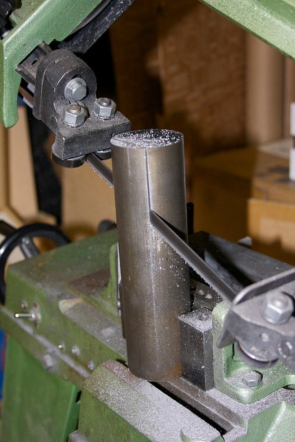
). The bandsaw made quick work of cutting to length:


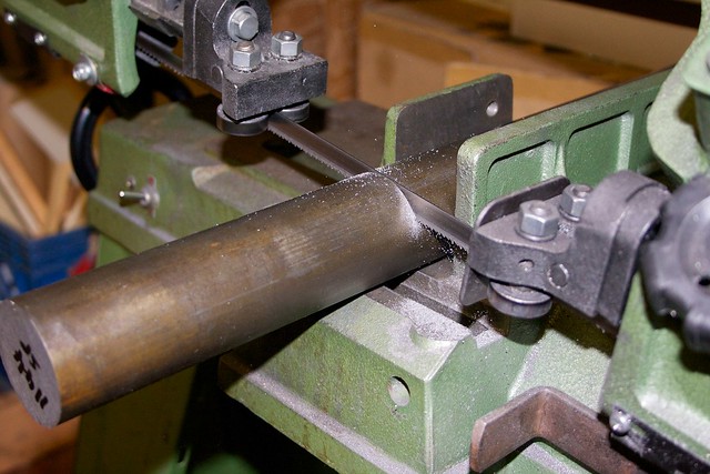
and then was used to cut a flat (slightly hairy clamping here, but it worked out OK):


As I have been well trained to do by now, first order of business is mill down the sawed face to a good flat surface:


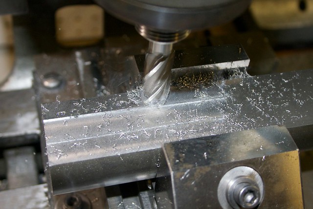
and with a few more cuts, we have two billets of material for the two conrods:


I've taken to writing the material on offcuts (and spent a happy couple of hours trying to identify some mystery rods by spark testing, which actually worked better than I imagined  :cartwheel: ) so my metal collection is a bit more organized now.

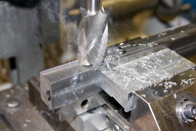
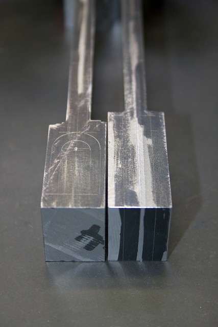
Using the rougher to get through the skin:


and then squaring up:


At first I didn't think I liked this material, but it's grown on me.

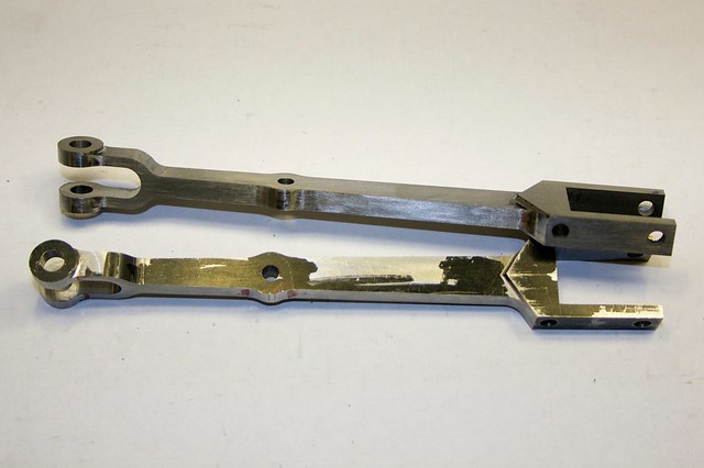
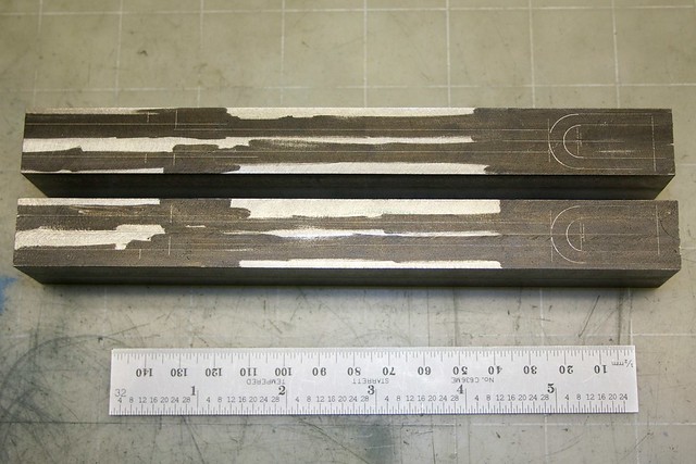
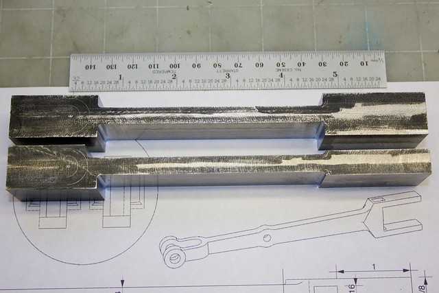
So, here we are, ready for the real work:


All marked out and ready to rumble:


First order of the day was removing the bulk of the material from each side of the rods. If they are going to warp, they'll do so after this material removal, so I didn't want to do any precision parts before cutting things down. No pictures of that, but it was mainly end milling with the rougher in the vise.

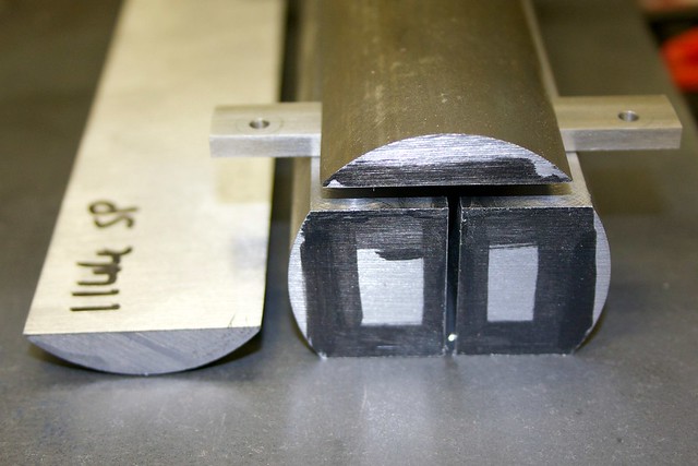
And, yup, even though this is "stressproof" there's some warping. The other ends are clamped together:


Now we can get closer to final dimensions. First, I thinned the big end:


and used a radius endmill to take the various parts down to near final thickness:


Not getting a very good finish from that end mill: I think it's getting a bit dull. I also used a ball-end mill to profile the join between the forks and the main body:


So we're left with:


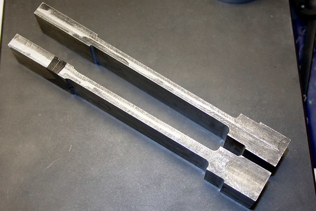
I was careful to do the operations in an order that left me with ways of holding the parts accurately in the vise. So here we've still got full height, allowing me to find an accurate centerline for the holes, and to drill them straight.

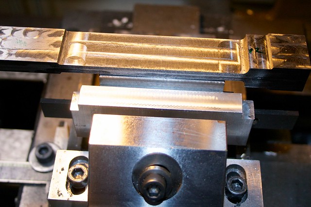
Because of the poor finish from the earlier milling, and still being a few thou over thickness, I wanted to take another skim of the shanks. To avoid any kind of taper, I use the "mill a parallel in place" trick, which is the bit of Al you see in the front here:


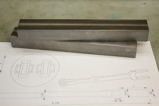
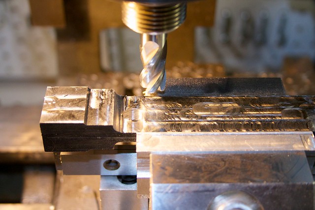
So now all the side faces are accurate. Time to start with some shaping! From the drawings in the eighth photo, you can see that these rods have a sort of "arrow" profile on the sides. To cut these, I set the vise at an angle:


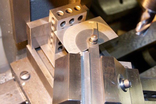
then used the no-so-sharp radius end mill (which has a 60 thou radius), being careful to just touch the previously cut surface:


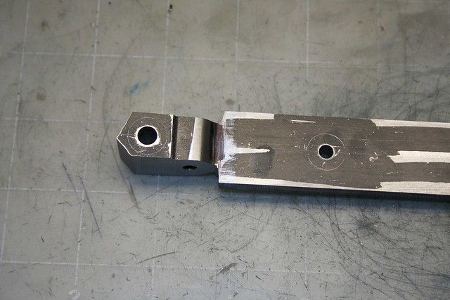
An end stop, in the form of a bolted-down 1-2-3 block, allows all four cuts at the same angle to be repeatable. For the other angle, the vise had to be repositioned the other way. You can see the resulting chevron profile on the left here:


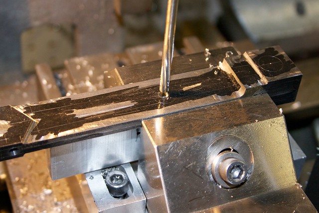
and, also, now is a good time to drill the holes. This middle hole drives the valve linkage, and I drilled the forked end in the same setup (using my poor man's DRO to measure the offset accurately).

Some other holes were drilled on the other axis:


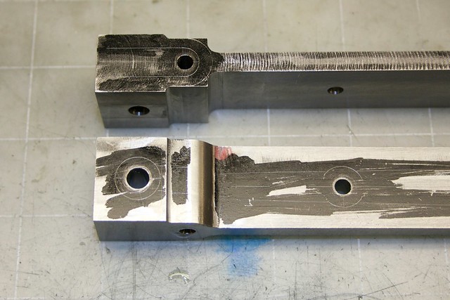
The big end has a hole for the pin that locates the closing block, and a hole that will be opened into a rectangle to take the cotter. On the right end is a hole that will be used to locate the part on the rotary table to round the shoulders (it gets milled away later).

Speaking of rotary tables, that's the next operation. To locate the part on the table, I use a 2-MT collet and a set of pins I made with various diameters that fit into a bit of 1/2" rod with a 1/4" hole in the middle. These get a lot of use!


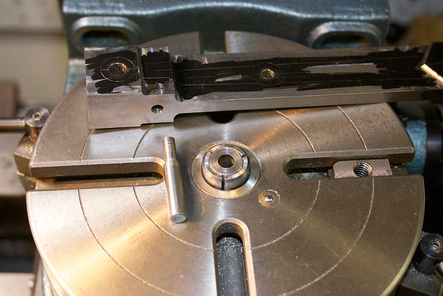
I was a bit concerned about the length of cut when rounding these shoulders, but it went without hiccups (as I said, this material is growing on me)


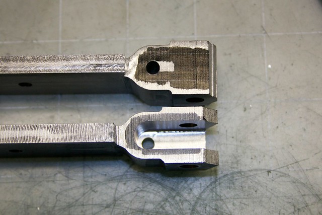
Now, while I still have straight top and bottom edges, I need to cut the space for the bearing blocks. Chain drilling and the bandsaw remove most of the material (and the waste will be used for the end stop):


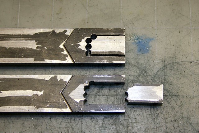
and then a saw takes out the rest:


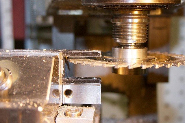
Since I always found sawing to be a somewhat mysterious operation, but now get along quite well with them, some words about how I did this might be useful.

First, use an appropriate speed! Calculate the RPMs based on the blade diameter; with larger blades like this, they get pretty low (I was running on my lowest speed, 125RPM).

Second, make sure the part is clamped such that the sawing action isn't going to move the part around. Here I've got the minimal amount of material projecting from the vise jaws.

For this operation, I did a roughing pass followed by a finish pass. For the roughing pass, the part was aligned with the spindle, and simply advanced slowly into the saw blade. Not sure if it's normal, but pretty much all the blades I have seem to be somewhat eccentric, so you'll get cut/skip/cut/skip noises as you do this. I left about 5 thou on all sides (I touched the sawblade off on the top of the part to get my height adjustment set up).

For the finish pass, we need to make sure the "bottom" of the cut is square, so we have to do some cranking of the cross-slide. You want to avoid climb cutting too (where the blade is trying to push the part along in the same direction as the cut), so here's what I did. First, do a cut at final height at the bottom of the U, with the crossslide towards the back of the mill, so that after getting to depth, you can crank the cross-slide towards you to create a flat left side of the cut. Then back out, raise the blade by a little under its thickness, crank the cross-slide back, move the carriage back to go to deph, and crank the cross-slide towards you again, taking another cut. Continue until you get to the top, doing a pass over the inner top surface on the last cut.

One done, one to go:


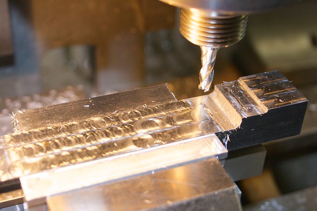
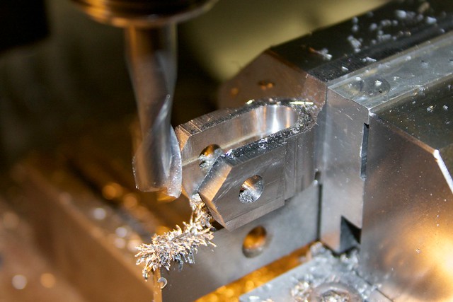
Now, one more operation we have to do while we can still hold the part horizontally accurately, and that's to cut out the yoke. First I thinned down the end on the bandsaw:


and then took out the bulk of the material with a 1/4" mill:


Note the bit of connecting material left to try to prevent those parts from flapping around later.

The slot is finished with a slot drill (2-flute end mill) for final width:


taking light cuts. One down, one to go:


I think that's enough for one post! I'll post part II shortly.

Simon


Offline smfr

  • Full Member
  • ****
  • Posts: 1203
  • San Francisco Bay Area, California
Re: Muncaster's Joys Valve Engine
« Reply #177 on: January 26, 2014, 05:42:53 AM »
The next set of operations are all about adding the taper to the top and bottom, and rounding.

I had one of those lying-awake-at-night bright ideas  :noidea: about how to mill the tapers. First, I decided to do it by side milling, because that takes care of the various radii at each end of the cut, and around the center hole. Then I realized I could locate the part on two pins, and just flip the part over to do the other side. Finally, I realized that I could drill and ream a fixture in situ for the pins such that the face to be cut was parallel with the mill axis. So with a bit of trig I worked out the X and Y offsets required to give the 1.2deg taper, and drilled and reamed some Al sheet for the two pins. Both parts slipped nicely onto the pins (it's great when math works  ;D ) and a wobbler follows the line  :cartwheel:


A nice carbide end mill (great estate sale find!) chews through this stuff like butter:


but I have to be careful to not go too far! The mill was chosen to give the correct 1/4" radius at the big end, around the central hole, and at the yoke end, so I mill up to the scribed circles (as close as I dare, at least!).

It's fun when the final shape of the part starts to emerge:


Both done!


Those shoulders need a bit of cleanup, so I use the same fixture set at the appropriate angle:


and then re-set to the other angle for the other shoulders.

Now we're on the home stretch! Just a bit of rotary table work to go! First around the central holes:


I always find this a bit nerve-wracking; it's too easy to turn too far and take out a chunk. One technique I've started to use is to mark the part with a Sharpie to see what's getting removed:


and a combination of this, and watching the handwheel to take small incremental cuts seems to work well.

Now to do the yoke ends:


again using those pins to easily locate the part. The final machining step is to cut the radius around the bosses with a radius end mill:


I only had time to do a bit of drawfiling on one of them, so there's quite a bit of finishing left:


but I'm quite happy with those. That'll do.

Simon

Online Kim

  • Global Moderator
  • Full Member
  • *****
  • Posts: 7946
  • Portland, Oregon, USA
Re: Muncaster's Joys Valve Engine
« Reply #178 on: January 26, 2014, 06:07:47 AM »
Wow Simon! You should be pleased with those con rods!  :NotWorthy: They look fantastic!  A lot of work and a lot of steps, but your careful planning really paid off I'd say!   Well done!
Kim
« Last Edit: January 27, 2014, 03:04:19 AM by krt2 »

Offline fumopuc

  • Full Member
  • *****
  • Posts: 3261
  • Munich, Germany, EU
Re: Muncaster's Joys Valve Engine
« Reply #179 on: January 26, 2014, 07:55:21 AM »
Hi Simon, very good job and documentation how to do it. Thanks for all your efforts and perfect presentation. This is the right place for my to learn
Kind Regards
Achim


SimplePortal 2.3.5 © 2008-2012, SimplePortal