Author Topic: Muncaster's Joys Valve Engine  (Read 160042 times)

Offline Jasonb

  • Full Member
  • *****
  • Posts: 9493
  • Surrey, UK
Re: Muncaster's Joys Valve Engine
« Reply #135 on: December 28, 2013, 01:48:46 PM »
Simon if you are putting oil boxes onto the bearing caps perhaps I could talk you into matching ones on teh eccentric straps as attached :LittleDevil: Few more photos to follow later.

The ones I posted above are part of the Fowler archive, they along with a lot more are on a forum I donate to so get access to that area of the site. You may find some on the following link but its been a while since I looked through it so not sure if its got any similar engines and its a bit slow going to look through them all as there are no thumbnails.

http://vios1.rdg.ac.uk/olib/images/nof/fowler/photos/

Offline smfr

  • Full Member
  • ****
  • Posts: 1203
  • San Francisco Bay Area, California
Re: Muncaster's Joys Valve Engine
« Reply #136 on: December 28, 2013, 05:24:45 PM »
Jason, if this engine had any eccentrics I'd do it  :Lol: (Actually if I decide to put on a pump at some point it would have one.)

After staring at this photo for a while I'm thinking of fixing my boo-boo of thicker flanges on the bearings fitting into recesses in the main casting. It won't look right  :thinking:

Simon

Offline smfr

  • Full Member
  • ****
  • Posts: 1203
  • San Francisco Bay Area, California
Re: Muncaster's Joys Valve Engine
« Reply #137 on: December 28, 2013, 07:47:59 PM »
Here's the plan for bearing caps with oil boxes:


Simon

Offline Jasonb

  • Full Member
  • *****
  • Posts: 9493
  • Surrey, UK
Re: Muncaster's Joys Valve Engine
« Reply #138 on: December 28, 2013, 08:01:22 PM »
The boxes will look good, that strap nearest the camera is the one for the pump. I also took a few more including a couple of the cylinder (and valve chest) drain arrangements.


Offline smfr

  • Full Member
  • ****
  • Posts: 1203
  • San Francisco Bay Area, California
Re: Muncaster's Joys Valve Engine
« Reply #139 on: December 31, 2013, 04:56:59 AM »
Very handy photos, thanks Jason! I'm thinking about that fetching curved profile on the top sides of the main casting, but my valve chest is on top, unlike this engine. I'll have a play in the CAD package   :headscratch:

With a bit of fussing around I got the main bearings fitted. I was careful to make sure they bear on the inner faces, not the flange edges. Sharpie marker is useful here to see which bits are touching:


Fitting was by a combination of filing and taking off a few thou here and there on the mill. When tidying up the bearings, I always put parallels under the critical inner faces, not the non-critical flanges for accuracy:


and always with the same reference face against the fixed jaw.

In situ, they are a nice snug fit :cartwheel:


with a proto bearing cap in the background. Those still have a bit of fussy rotary table work.

I also got the bearing standards drilled and tapped today:


which means I can make some temporary bearing caps to hold the bearings down if I choose to line bore them.

The other small bit of progress was to get the cylinder block fixed to the base, which involved making 6 2BA studs:


I haven't quite got the hang of making these short studs yet. I cut the longer thread while still on the parent material, then parted off, turned around in the collet and threaded the shorter end. However, threading the second end would cause them to spin around in the collet and get chewed up, so I made a small fixture out of a bit of 1/2" SS with a built-in backstop. However, this didn't hold the studs securely until I drilled and reamed a bit to fit the unthreaded section, and after that I had one of two problems. :wallbang: Either I wasn't able to easily remove the finished stud from the fixture (had to resort to a pair of locked nuts), or reversing the die caused the stud to unscrew from the fixture:


The only thing I can think of to make this easier is to adjust the fixture to expose a section of the stud thread on the inside, and use a locknut there to hold for the second threading op. Any other ideas?  :thinking:

Feels good to get these parts hooked together, which took a little bit of easing of the holes in the cylinder block, but not too much:


The studs need a bit of length adjustment. I also discovered that I can't drop the nuts over the studs without raising the cylinder block a little, which is going to make assembly/disassembly a whole lot of fun ;D

Simon

Offline fumopuc

  • Full Member
  • *****
  • Posts: 3261
  • Munich, Germany, EU
Re: Muncaster's Joys Valve Engine
« Reply #140 on: December 31, 2013, 08:17:21 AM »
Hi Simon, great progress, it is looking better and better. Your way to make the bearing and bearing cap is something I have to learn.
« Last Edit: December 31, 2013, 06:19:36 PM by fumopuc »
Kind Regards
Achim

Offline NickG

  • Global Moderator
  • Full Member
  • *****
  • Posts: 1430
Re: Muncaster's Joys Valve Engine
« Reply #141 on: December 31, 2013, 01:50:18 PM »
Well done Simon, it really looks the part.  :NotWorthy:

Offline RonGinger

  • Full Member
  • ****
  • Posts: 302
  • Boothbay Maine USA
    • Pleasant Cove Models
Re: Muncaster's Joys Valve Engine
« Reply #142 on: December 31, 2013, 05:24:48 PM »
I have had good luck holding small threads by taking a hex nut of the right size and sawing a slot from one flat into the center. I can then clamp the hex nut in a 3, or 6, jaw chuck. It seems to grip the thread well enough for things like making a stud or reshaping the head of a bolt. I have several sizes like this on the top tray of my lathe.

Offline smfr

  • Full Member
  • ****
  • Posts: 1203
  • San Francisco Bay Area, California
Re: Muncaster's Joys Valve Engine
« Reply #143 on: December 31, 2013, 05:34:39 PM »
I have had good luck holding small threads by taking a hex nut of the right size and sawing a slot from one flat into the center. I can then clamp the hex nut in a 3, or 6, jaw chuck. It seems to grip the thread well enough for things like making a stud or reshaping the head of a bolt. I have several sizes like this on the top tray of my lathe.

Oooh, that's a good idea Ron, I'll have to try that!

Simon

Offline Don1966

  • Full Member
  • *****
  • Posts: 6818
  • Columbia, MS
Re: Muncaster's Joys Valve Engine
« Reply #144 on: December 31, 2013, 06:37:48 PM »
Simon I can appreciate the bearing blocks, because I know you put a lot of effort in making them. Nice work as usual.

Don

Offline smfr

  • Full Member
  • ****
  • Posts: 1203
  • San Francisco Bay Area, California
Re: Muncaster's Joys Valve Engine
« Reply #145 on: January 02, 2014, 06:35:46 AM »
Time to talk about the valve plate  :D

As I mentioned earlier, Muncaster designed this engine to be easy to make (no angled drilling of steam passages), and to maintain, so he has a valve plate that sits between the cylinder block and the valve chest. He says to make this from steel, but I used cast iron.

A slice was taken off the lump that donated the cylinder block, on the bandsaw:


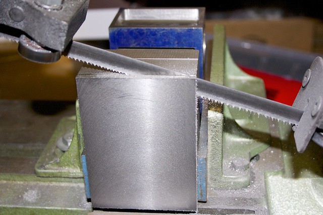
and the rest of that lump will become the valve chest. It's nice to be able to get a reasonably straight cut and slice of a thin piece like this; there's no way I could do this with a hacksaw  :insane: I made sure to flycut the block before sawing, to give me a flat surface to work with  :ThumbsUp:

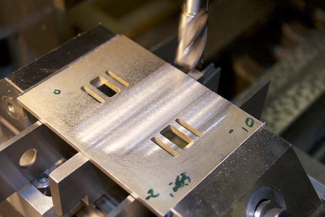
I decided to machine this 1/8" plate by glueing it to the other part of this cast iron lump, so that needed a flat surface too. I've got into the habit of running an indicator over uneven surfaces once mounted in the vice and writing on the high and low spots:


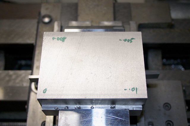
so I know how many passes I need to take and how much to remove on each pass. Once that surface was flat, I superglued the plate to it:


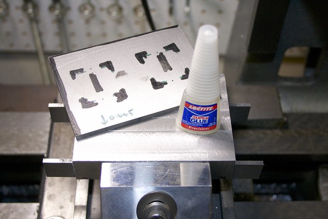
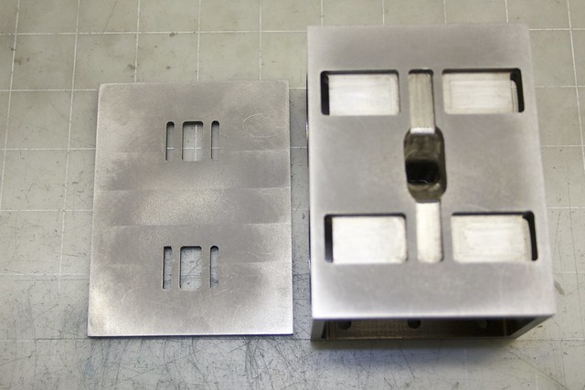
after marking out the valve surfaces. After an overnight cure, 1/32" was removed from the bulk of the plate, leaving two raised areas on which the valves bear. I presume this is to allow for wear if the engine is run for long periods of time:


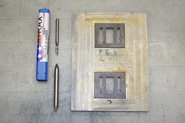
Then the valve openings were marked out:


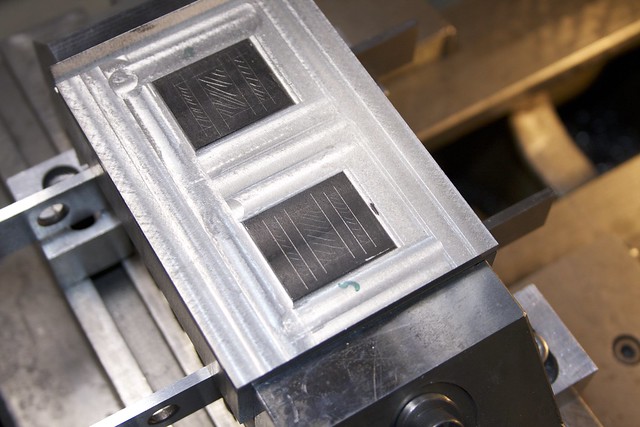
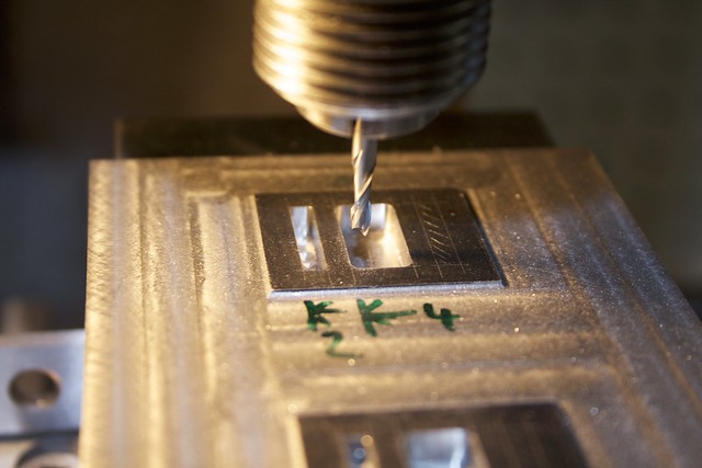
making it obvious which bits to remove. There's nothing worse than milling out between the wrong pair of lines! Those are 1/8" slots, and I find that using a 1/8" endmill gives me slots a few thousands wider, so needed something smaller. I had ordered a 1/16" end mill for this purpose, and after drilling out some of the material, gingerly started in with small cuts. On the first slot, then first end broke. On the second slot, the other end broke when I just looked at it wrong :facepalm2: (Remind me not to buy Chinese-made Interstate mills again.)

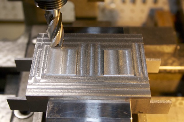
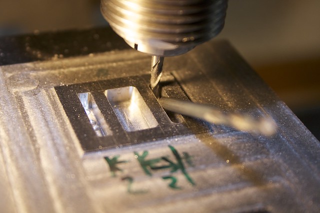
After a couple of days of waiting, the brown truck delivered a nice 7/64" carbide bit, which was so much nicer to work with:


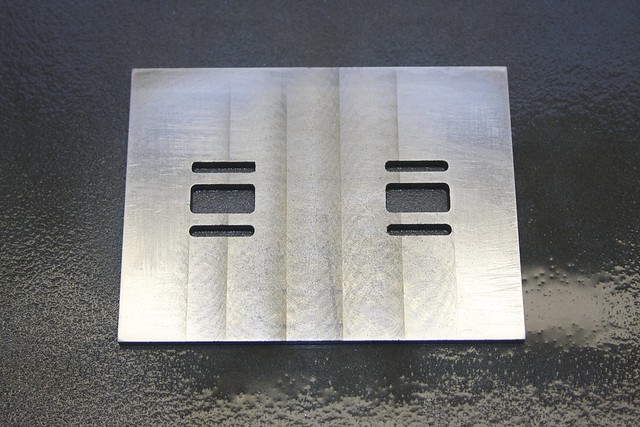
and resulted in some nice accurate slots; here I'm checking slot width with a 1/8" drill bit:


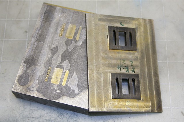
Now with a bit of heat and a struggle the plate was separated from its parent block:


Here's a shot that shows the broken vs. quality end mill:


Now to clean up the surface with some wet&dry on the glass plate:


Uh oh, something's not flat  :Doh: My plate seems to have warped pretty badly (a few thou in the middle). So it was back onto the mill with it for a skim:


but back on the glass plate, the sides are high now!   :facepalm:


Almost and hour of rubbing on wet&dry and filing didn't want to correct that, so I looked around for other abrasives, and spotted the Timesaver compound. Since I had that mixed up, I might as well do the top of the cylinder block, and, hey, isn't there something about rubbing three surfaces together gives you a perfectly flat one (the third is a face of what will be the valve chest)?


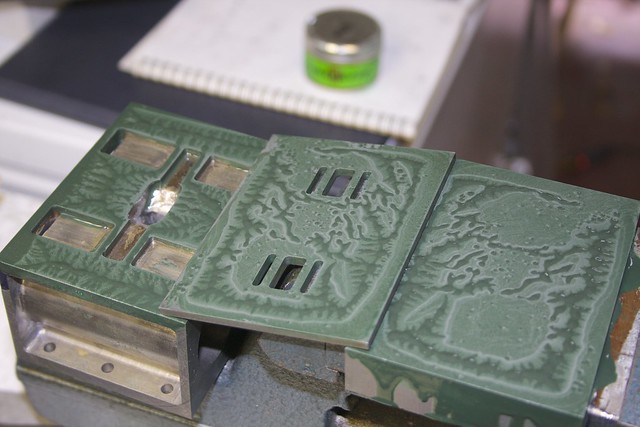
A treatment of coarse followed by medium compound did a reasonable job:


I'm not getting out to the sides and corners as much as I'd like. And see that shiny spot in the middle of the valve plate? Yeah, that means the plate is high in the middle again...but that's probably OK since clamping it down around the edges should result in a good seal around the steam passages. Not sure if I'll have a gasket under the valve plate?

The valve-bearing surfaces also got a rub with the Timesaver compound, so they should be almost ready to take the valves.

So that'll do for now. I'll probably have another go at those surfaces once it comes to assembly time. Making flat surfaces is hard :( I guess that's where a surface grinder comes in handy!

Next will be the valve chest, which I'm hogging out of that lump of iron. And this stack of parts is topped off with a valve cover, which will be yet another slice of CI.

Simon

Offline Jasonb

  • Full Member
  • *****
  • Posts: 9493
  • Surrey, UK
Re: Muncaster's Joys Valve Engine
« Reply #146 on: January 02, 2014, 07:53:13 AM »
I suspect your plate curled as it was sawn off the large block.

The reason the two valve surfaces are raised is so its easier to lap a small area. Also on the real thing where the valve surface would have needed machining down in the bottom of the valve chest cavity it gave the planning machine some run out at the ends of the stroke.

I'd use CSK screws to hold the plate to the block and add a slow setting epoxy, once its all screwed down lap your valve faces again as things are likely to move again when screwed down. I've seen it done a few times this was to correct poorly cast valve ports. The plate stays as part of teh block and you have a separate valve chest so you may need to think about screw positions to miss the studs which should pass through the plate and be screwed into the block and miss the CSK screws.

J

Offline smfr

  • Full Member
  • ****
  • Posts: 1203
  • San Francisco Bay Area, California
Re: Muncaster's Joys Valve Engine
« Reply #147 on: January 02, 2014, 05:26:54 PM »
Hmm, interesting suggestion Jason to expoxy them together. I was going to keep them separate, but I do suspect that without a gasket, I'm going to get some leakage around the steam ports. Another option would be a smear of silicone or similar on assembly.

In terms of lapping, once I've drilled the holes for the valve chest studs I could possibly bolt down the valve plate from the sides for a final lapping (using something that fits between the studs). Not quite ideal, but should be good enough?

I'll have to think about it  :thinking:

Simon


Offline Florian Eberhard

  • Full Member
  • ****
  • Posts: 437
Re: Muncaster's Joys Valve Engine
« Reply #148 on: January 03, 2014, 11:33:29 PM »
Hey Simon

What about assembling the cylinder block and the valveplate with a liquid sealant?
I think i will finally do it that way with my stuart pump...

Florian

Offline Jasonb

  • Full Member
  • *****
  • Posts: 9493
  • Surrey, UK
Re: Muncaster's Joys Valve Engine
« Reply #149 on: January 04, 2014, 08:01:43 AM »
My reason for suggesting fixing the plate separately are that you can lap it flat once it has been fixed as tightening down is likely to cause slight distortion, by doing it with a permanent adhesive the subsequent tightening of the chest will not add any distortion, even a smear of silicon gasket is still flexible.

If you put it all together in one go using the same studs as the valve chest you really have no easy way to lap and if the valve chest or cover needs to be removed you will need to lap again when its retightened as its unlikely to go back the same.

Muncasters loose plate is really just an easy way to reproduce a single casting that would have had the passages cast in so by fixing the plate to the main block you are once again treating these two as a single casting.

J


SimplePortal 2.3.5 © 2008-2012, SimplePortal