Author Topic: Muncaster's Joys Valve Engine  (Read 160202 times)

Offline fumopuc

  • Full Member
  • *****
  • Posts: 3261
  • Munich, Germany, EU
Re: Muncaster's Joys Valve Engine
« Reply #105 on: December 06, 2013, 11:00:11 AM »
Hi Simon, now I have had the time to look through the whole thread first time.
I like your way and style to build an engine very much.
It shows very good that with simple methods the final things can look like the originals.
I will follow your up dates every time.
Achim
« Last Edit: December 06, 2013, 12:26:16 PM by fumopuc »
Kind Regards
Achim

Offline smfr

  • Full Member
  • ****
  • Posts: 1203
  • San Francisco Bay Area, California
Re: Muncaster's Joys Valve Engine
« Reply #106 on: December 06, 2013, 05:11:41 PM »
Thanks Achim!

Jason and Florian, thanks for the advice. Jason, I thought that zero top rake was normal for cutting cast iron?

I read up and see that a diamond hone is the best way to get a good finish on carbide tools, and my estate-sale grinder came with a diamond wheel, so I'll give that a try!

Simon

Offline Florian Eberhard

  • Full Member
  • ****
  • Posts: 437
Re: Muncaster's Joys Valve Engine
« Reply #107 on: December 06, 2013, 05:21:59 PM »
Hi Simon

If you have very unstable condition, it can help to give a little top rake. (I would try with 5° for example)
The Reason is the easier flow of the chips when having a smaller wedge angle (and therefore smaller cutting forces)

Florian

Offline smfr

  • Full Member
  • ****
  • Posts: 1203
  • San Francisco Bay Area, California
Re: Muncaster's Joys Valve Engine
« Reply #108 on: December 07, 2013, 05:43:48 PM »
I gave the carbide cutter a trial run last night (boring the ring gauge) and it promptly chipped. I might just use HSS from the get-go, just have to find something to grind down.

Would oil-hardened drill rod also work as a cutter?

Simon

Offline Jasonb

  • Full Member
  • *****
  • Posts: 9495
  • Surrey, UK
Re: Muncaster's Joys Valve Engine
« Reply #109 on: December 07, 2013, 05:47:11 PM »
An old centre drill or milling cutter will grind up OK. Drill rod maybe OK but could dull a bit quicker.

J
« Last Edit: December 07, 2013, 05:50:25 PM by Jasonb »

Online Jo

  • Administrator
  • Full Member
  • *****
  • Posts: 15306
  • Hampshire, england.
Re: Muncaster's Joys Valve Engine
« Reply #110 on: December 07, 2013, 05:48:20 PM »
Would oil-hardened drill rod also work as a cutter?

Yesterday I have happily cut a dovetail in cast iron using water quenched drill rod.

Jo
Enjoyment is more important than achievement.

Offline smfr

  • Full Member
  • ****
  • Posts: 1203
  • San Francisco Bay Area, California
Re: Muncaster's Joys Valve Engine
« Reply #111 on: December 09, 2013, 04:37:22 AM »
Had a very boring day today...and it was a success  :whoohoo:

First I raided my broken tools box for a bit of 3/16" HSS, and found a broken BA tap with the right diameter, so I ground a bit of a groove where I wanted it to break, and broke it in the vise (covered with a cloth, hit it with a hammer!), then ground it down. It's the one on the right here:


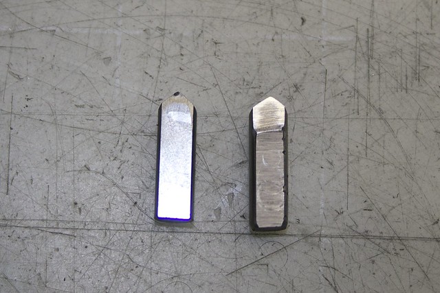
with the carbide on the left. The only critical dimension was that the flat at the end needed to be at the same depth as that on the carbide, because I drilled the hole in the boring bar to put this flat on center.

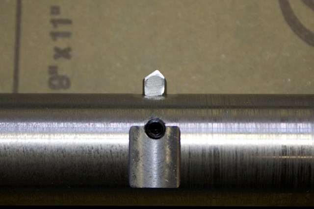
Jason, I put angles on both sides so that I could take boring passes in both directions, at least for roughing. Here it is in situ


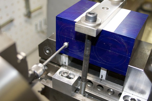
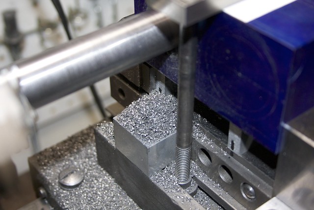
I set up the cylinder block again in the vise, and got everything dialled in. However, I wasn't happy with my adjustable parallels under the block, as I measured just under a thou difference between one end and the other on the larger parallel. So I trimmed down a couple of bits of aluminum plate, holding them in the vise at the locations where they would be used (note the Sharpie marks on them the two bits of plate, and corresponding marks on the vise):


After measuring the center height of my lathe, I could compute how tall these parallels needed to be to give me my correct hole center. Milling them in situ ensure the correct height, and accurate flat tops for the workpiece to sit on.

Here's my final setup, complete with the a nice steel clamping bar on top, with holes matching my T-slot spacing. That bar ensures that the block is held down tight onto the parallels. I'm checking the center height with a wobbler:


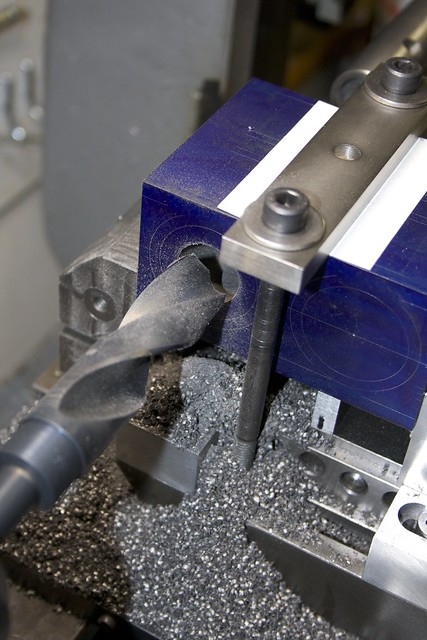
And we drill! I started with a spotting drill, then drilled with something around 1/4", working my way up by roughly 3/64" intervals.

The flutes on the smaller drills weren't long enough to provide chip clearance near the bottom of the hole, and this is what happens
if you don't have enough chip clearance and the drill seizes  :hammerbash:


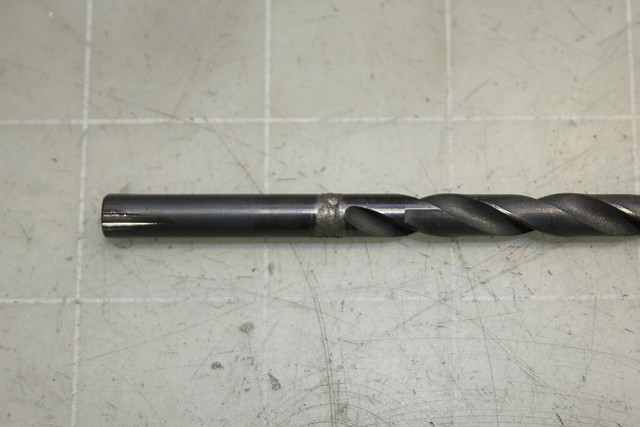
Luckily the belts would slip on the lathe before anything bad happened :) After that I was more cautious and peck-drilled to clear chips.

Pushing the part with the tailstock ram worked a treat.  :ThumbsUp: I used my tailstock die holder as a pusher, since it has a convenient hole in the center that allowed clearance for the drills to emerge from the block.

Eventually I made it up to the cheap Chinese Silver and Deming drills I got at a yard sale:


and things got a bit dicey. These things have so much runout you wouldn't believe it  :o. As a result, the side flutes don't clear the chips properly, and they get wedged around the sides, causing sticking:


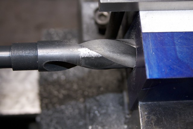
You can see that I took a file to it to increase the clearance, and find I could easily file here; seems like only the tips are hardened?

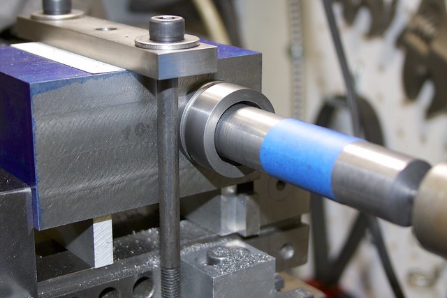
After those big bad drills it was a relief to get to the boring! I set up the boring bar between the 3-jaw chuck and a live center, and started with the carbide bit. I found a half turn of the adjustment screw (32 TPI, so 0.03125" per turn, 16thou for a half turn) was good for a roughing pass, with the lathe running at 210RPM and using the power feed. I cut in both directions while roughing. The chips look good!


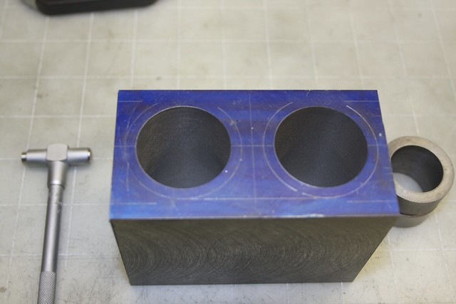
I'm glad I marked out the diameter; it made it easy to decide when to switch to the HSS bit at the point where I had maybe 3-4 passes to go. I'm also really glad that my ring gauge had two diameters about 6 thou apart. Here the first slips in:


so I know I need to advance the tool by about 3 thou. At this late stage I used an indicator to measure tool advance:


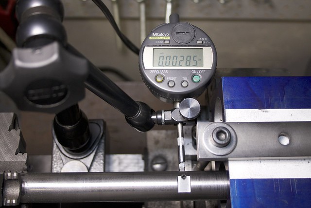
and found that I could easily adjust to a few tenths this way. I made a final spring cut at the end, but there was almost no spring with this rigid setup. When I was more organized on the second bore, I also made sure to only do the final cuts in one direction (moving towards the headstock), since the power feed can cant the carriage slightly.

When the first bore was done, I used both an indicator and the dials to move the crosslide by the required 2" (got 10thou of disagreement :o and went with the indicator), then checked center with the wobbler on the second bore. Drilling and boring went much as before, and I was lucky to get the second bore almost a dead match for the first. A bore gauge shows them both close to 1.375", so I'll take that! I'm also quite happy with the finish; I think they'll hone nicely.


Phew! Feels like a hurdle cleared to get that done  :pinkelephant:

Next is making a mandrel to hold the block while I do some shaping of the outside on the rotary table.

Simon
« Last Edit: December 09, 2013, 05:17:07 AM by smfr »

Offline tvoght

  • Full Member
  • ****
  • Posts: 1003
  • Indiana
Re: Muncaster's Joys Valve Engine
« Reply #112 on: December 09, 2013, 05:04:23 AM »
Excellent.

--Tim

Offline vcutajar

  • Full Member
  • *****
  • Posts: 2555
  • Marsascala, MALTA
Re: Muncaster's Joys Valve Engine
« Reply #113 on: December 09, 2013, 07:43:11 AM »
Well done Simone.

Vince

Offline GailinNM

  • Full Member
  • ****
  • Posts: 588
  • Albuquerque, NM, USA
Re: Muncaster's Joys Valve Engine
« Reply #114 on: December 09, 2013, 01:10:02 PM »
Great tutorial on your boring setup Simon.
Thanks.
Gail in NM
I would like to be the kind of person my dog thinks I am.

Offline Dave Otto

  • Full Member
  • *****
  • Posts: 4712
  • Boise, Idaho USA
    • Photo Bucket
Re: Muncaster's Joys Valve Engine
« Reply #115 on: December 09, 2013, 01:23:13 PM »
Nice work Simon


Dave

Offline Don1966

  • Full Member
  • *****
  • Posts: 6818
  • Columbia, MS
Re: Muncaster's Joys Valve Engine
« Reply #116 on: December 09, 2013, 07:40:06 PM »
Simon, thats a nice setup and like you I hold my breath till the last hole is done.

Don

Online Roger B

  • Global Moderator
  • Full Member
  • *****
  • Posts: 6172
  • Switzerland
Re: Muncaster's Joys Valve Engine
« Reply #117 on: December 09, 2013, 07:51:51 PM »
Good and interesting stuff to bear in mind when I bore out my next cylinder  :ThumbsUp:
Best regards

Roger

Offline smfr

  • Full Member
  • ****
  • Posts: 1203
  • San Francisco Bay Area, California
Re: Muncaster's Joys Valve Engine
« Reply #118 on: December 16, 2013, 06:59:01 AM »
This cylinder block is becoming more like a casting now, after lots of profiling work.

But first, we need a way to easily locate cylinder bores on the rotary table, so I made a mandrel, first turning a 1/2" diameter on one end to fit my rotary table spindle (in an MT2 collet), and then holding by that to turn the outer diameter to a nice fit to the cylinders:


Now I could use it to see how far off my cylinder bores are:


Looks like I'm 2 thou off, which I can live with  :cartwheel:

Now, each side has material removed to reveal the curve of the cylinder. I do some rough milling first, then I'll use the rotary table to get the curve. I made myself a roughing chart in my CAD program:


After a few passes with the 3/16" ball end mill, I realized that things would be much quicker if I removed the bulk of the material with a larger end mill:


Getting some nice chips there!

This is after roughing out with the ball-end mill, which I used because it's more forgiving if you make mistakes (circular dimple rather than sharp-edged hole!):


OK, now we can set up on the rotary table, using the mandrel for easy centering:


and a flat-ended end mill makes nice work of the convex surfaces:


I did facets every 2deg on the finish pass, which should be relatively easy to sand down to a smooth surface.

Finally I did a pass around the edges using a longer ball-end mill, this one a mystery cutter obtained in some job lot, but relatively sharp:


I needed the length for clearance, but it means this cutter sure does like to flex! Repeated passes over the same surface would keep cutting, so care was needed!

Lather, rinse, repeat and the other side was done. Now to the underside. Although this will never be seen, I still wanted the cylinder curvature to show up here to give the illusion of this being a casting, and there's a ridge down the middle through which the exhaust comes out.

Again I removed the bulk of the material with a 3/8" cutter (with a small edge radius; I'm getting fond of radiused cutters!):


Done, leaving some material for the radii:


While I had the vise set up, I did the operations on the top surface too: drilling for the exhaust, and cutting out the steam channels.

Space is a bit tight between the cylinders, so I wanted an oval hole 5/16" by about 1/2". That meant drilling two intersecting holes, which is always a bit hairy. I drilled both holes out until they joined:


but of course the next drill up stated to wander into the other hole, so I had to switch to an end mill to finish the job (and go in from both top and bottom, since it's a deep hole):


Muncaster designed this engine to be relatively easy to make, so he avoided drilling steam ports, and instead use a valve plate over channels in the cylinder casting. So I have to mill some channels:


Here's the exhaust channel connected to the previously drilled hole:


and you can see that I've already cut the 1/8"-wide cylinder ports.

This final steps today were profiling the never-to-be-seen underside bits:


Here I got smarter and used a narrow end mill, which makes it possible to get further into the corners when rounding. There's something very satisfying about seeing a nice round profile emerge from a roughly milled pocket  :pinkelephant:

Both sides done, and all that's left on this underside is a trip around the edge of the second pocket with the ball-end mill:


That exhaust port will be covered by a gland connecting to a bit of copper pipe (3/8"?) with a 90deg bend which will exit through the base. According to Alan Stepney, 3/8" is about the right size here.

What's next? Lots of fettling on the cylinder block, and some holes to be drilled to locate it on the base. Then I think I'll do cylinder covers and/or the valve plate.

Simon

Offline tangler

  • Full Member
  • ****
  • Posts: 834
  • Christchurch, UK
Re: Muncaster's Joys Valve Engine
« Reply #119 on: December 16, 2013, 09:04:52 AM »
Simon,

That's a really impressive investment of effort and skill into 1 lump of iron.  I'd have been shaking like a leaf on the final cuts!  Very nice.

Rod


SimplePortal 2.3.5 © 2008-2012, SimplePortal