Slow but sure progress continues!
Got both bearing caps profiled on the rotary table:
but I put this aside to focus on the base.
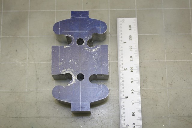
Inspection after the JB-Weld had cured showed a reasonably good result, but one end piece was a bit out of line and needed some cleaning up. At this point I could treat the base like a casting; take a file to the underside to get it to sit flat:
and then take a few thou off the high spots on the upper side to I can blend things together:
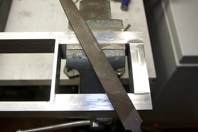
which required a bit more work on those curved profiles to get them to blend into the end flat. The end face also needed a lot of filing work:
so I attacked it with my biggest file, and eventually got things blended pretty well.
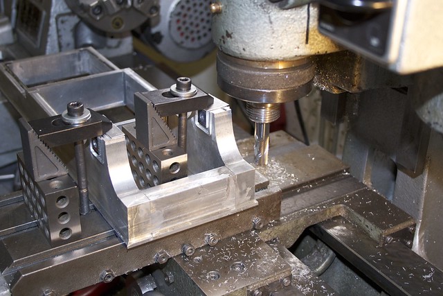
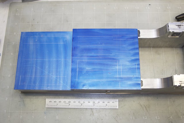
Now, to the top surfaces. I planned for the top plates to be 0.25" thick, but need a little more thickness, and I want to leave some surface features there to locate the crosshead slides, the cylinder block, and the valve pivot standards. So some 5/16" plate was cut to size and marked out:
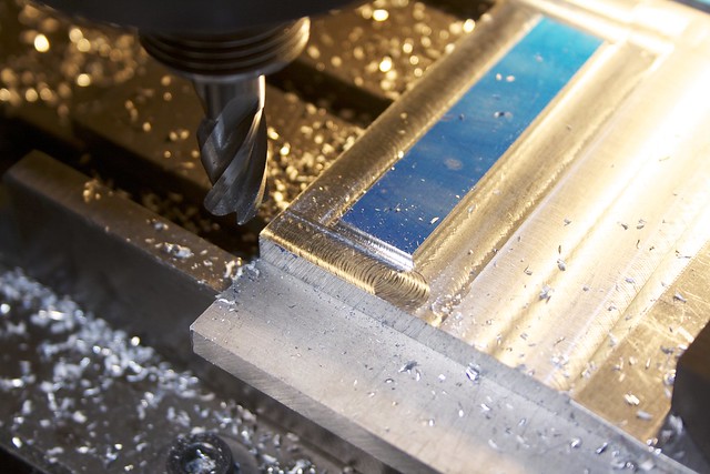
The corner-radius end mill was a handy way to get a radius for the surface features:
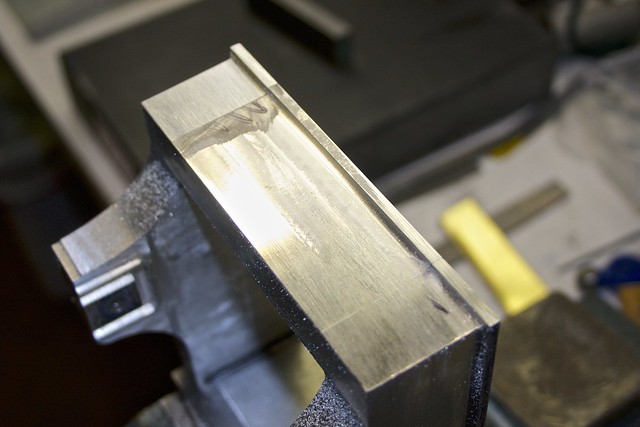
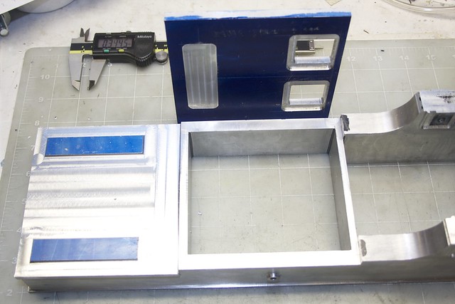
The underside of the upper plate needed some work too; a slight recess where the valve link pivot block is located, and some thinning around the two holes so the thickness looks more appropriate in that area.
I've been thinking

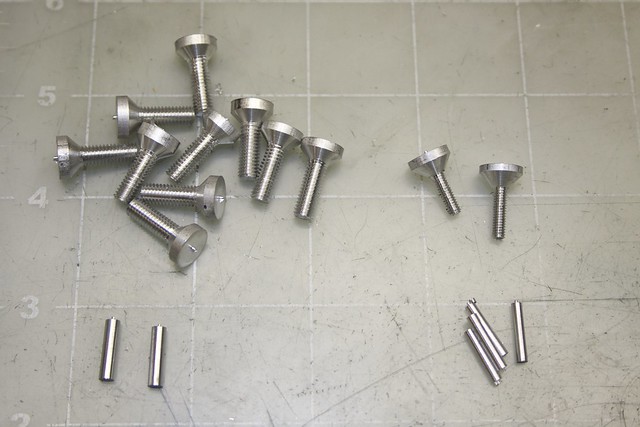
for a while about how to secure these top plates for JB-Welding. I could just rely on the JB-Weld, but I want some fasteners too. I could put in temporary screws, and later drill out and fill the holes, but I worry about the screws getting stuck in there with the epoxy. So I decided to make some aluminum, countersunk screws to hold the plates down, the tops of which will be milled off later. I needed 10-12 of these, so got my rhythm going like this:
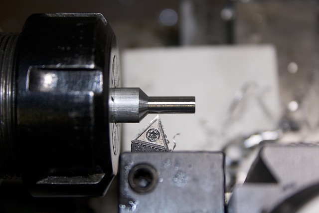
Get about 3/4" of bar projecting from the collet chuck, mark off 1/2" (thread depth) with a marker. 2-3 passes with the Al insert tool takes it down to a bit over 3/16":
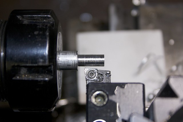
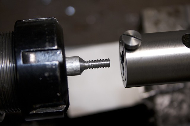
Swap to another insert that happens to give me a 45deg angle, align it with the end, set the carriage end-stop using a 1/2" drill bit, do a couple of passes to go down to final diameter and get the bevel (after the first one, I can use the dials to get to final diameter):
Swap the belts to go to low speed. Use a tailstock die holder to thread under power, stopping once to clear chips, and carefully holding the die holder by hand, letting it slip when it hits the bevel. Back off under power (low speed!).
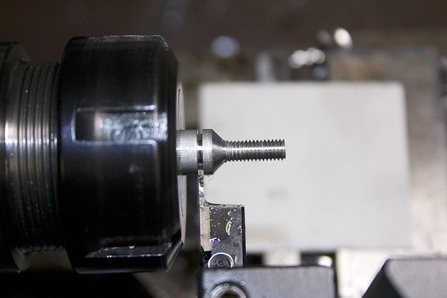
Back to high speed. Touch up the end of the threads with a file, swap to the parting tool and part off, leaving some material on the head to cut the slot:
And repeat!
I also turned some pins from bits of scrap to pin the joints where there isn't room for a screw:
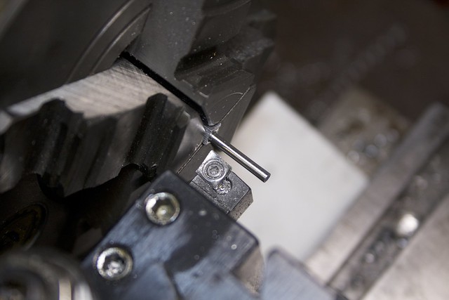
Without any support on the tailstock end, they come out with a bit of a taper, but that's just fine for what I want them for.
There that little lot, just needing some slots cutting (which I'll probably just do with a hacksaw):
Now the next stage is to get the top plates accurately positioned on the base to drill holes for the screws and pins. I have a accurate centerline on the plates, and took some time to line up the base on the milling table:
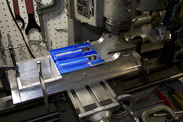
I have a plate clamped to the milling table with the engine base sitting on top. With a bit of bar though the temporary crankshaft holes, I used an indicator to get the base aligned as accurately as I could. Then I used an edge finder on the bearing standards to find the centerline, checking my result with a parallel adjusted to fix exactly on either side between the edge finder body and the standard.
And then it was time for dinner and

Hopefully I'll get some time during the evenings this week to get the JB-Welding done. Next steps are:
- Align plates to centerline, and clamp
- Drill, countersink and thread for the Al screws around the edges, and drill for the pins
- JB-Weld and fasten with the screws, let cure
- Mill non-critical surfaces down to final height, lots of corner-rounding
- Accurately mill channels for the crosshead slides, cylinder block pedestals, main bearing slots
- Finishing. Lots of finishing

Can't wait to get this base out of the way. I think the next part will be the cylinder block, and I've almost convinced myself to make it from two lumps of cast iron which I already have, rather than ordering a single 4"x4"x2" lump. Just need to figure out how to bolt them together.
There's also the matter of the exhaust. As designed, the exhaust from both cylinders passes through a passage between them and through a hole in the base casting to...nowhere. That seems like a great way to spread an oily puddle of water over the bench! So I think I'll put an exhaust pipe under the cylinder block and exiting through a hole in the base, but with my two-part cylinder block that means part of the exhaust passage intersects the join between the two sides, which could be leaky. Not really sure if that matters for exhaust, though?

Simon


