Author Topic: Muncaster's Joys Valve Engine  (Read 160070 times)

Offline Don1966

  • Full Member
  • *****
  • Posts: 6818
  • Columbia, MS
Re: Muncaster's Joys Valve Engine
« Reply #15 on: September 25, 2013, 01:17:29 AM »
Hi Simon, just catching up on your new built and I do want to tune in and watch it take shape. Looks to be a very interesting build.  :ThumbsUp:

Don

Offline ths

  • Full Member
  • ****
  • Posts: 1801
  • Kangaroo Valley, NSW, Australia
Re: Muncaster's Joys Valve Engine
« Reply #16 on: September 25, 2013, 02:33:38 AM »
I always think that with metals, epoxy does better with a bit of polygonal geometry to bond into. Hugh.

Offline V 45

  • Full Member
  • ****
  • Posts: 384
  • central PA...USA
Re: Muncaster's Joys Valve Engine
« Reply #17 on: September 25, 2013, 03:12:38 AM »
Hello Simon...nice start to another interesting build. I'll watch as you progress.
Dave
Never assume the implied task has been completed !!

Offline Noitoen

  • Full Member
  • ****
  • Posts: 108
  • Setúbal - Portugal
Re: Muncaster's Joys Valve Engine
« Reply #18 on: September 25, 2013, 10:17:09 AM »
You should get better bond with less work if the pins are from threaded rod ;) The holes could have a thread as well even if they don't "mate" with the pins.

Offline sshire

  • Full Member
  • *****
  • Posts: 3044
    • LS Editions
Re: Muncaster's Joys Valve Engine
« Reply #19 on: September 25, 2013, 01:17:38 PM »
Interesting engine,Simon. Great start as usual. This shows ow much you've thought about this. I try to think through the machining for my next part in my head before cutting metal. Will you post the plans?
Best,
Stan

Offline b.lindsey

  • Global Moderator
  • Full Member
  • *****
  • Posts: 13860
  • Dallas, NC, USA
    • Workbench-Miniatures
Re: Muncaster's Joys Valve Engine
« Reply #20 on: September 25, 2013, 03:17:48 PM »
Simon, its looking good so far. I think the pinning and JB Weld should hold up fine given what you said about testing the joints so far. Worst case scenario is you might have to re-glue the joints some day, but I doubt that will be soon. If you decide to mount it to a wooden base as some point into the bottom of the frame members, that would further reinforce the whole structure too. Looking forward to seeing more on this one !!

Bill

Offline sshire

  • Full Member
  • *****
  • Posts: 3044
    • LS Editions
Re: Muncaster's Joys Valve Engine
« Reply #21 on: September 25, 2013, 08:46:32 PM »
Simon
Im sure you've seen these, but others may be interested

http://www.replicaplans.com/MuncasterSteamEnginePlans.html
Best,
Stan

Offline smfr

  • Full Member
  • ****
  • Posts: 1203
  • San Francisco Bay Area, California
Re: Muncaster's Joys Valve Engine
« Reply #22 on: September 25, 2013, 09:08:15 PM »
Im sure you've seen these, but others may be interested

http://www.replicaplans.com/MuncasterSteamEnginePlans.html

Thanks Stan, I have! This engine isn't on the list, though!

As for posting the plans, the 3D package I'm using does a terrible job of making 2D drawings :( I could try to export a .dwg or .dxf but I don't know how well it would transfer to AutoCAD.

Simon

Offline Bearcar1

  • Full Member
  • ****
  • Posts: 829
  • Chicagoland Area, USA
Re: Muncaster's Joys Valve Engine
« Reply #23 on: September 26, 2013, 12:09:39 AM »
Holy cow! Simon, nice work and I'll be watching as you proceed.  :ThumbsUp: :ThumbsUp:  Great start.


BC1
Jim

Offline sshire

  • Full Member
  • *****
  • Posts: 3044
    • LS Editions
Re: Muncaster's Joys Valve Engine
« Reply #24 on: September 26, 2013, 12:32:57 AM »
Simon
If u want to try an Autocad export, I can see how it does with the 2d
Best,
Stan

Offline Maryak

  • Rest In Peace
  • Full Member
  • *
  • Posts: 1818
  • Aldinga Beach South Australia
Re: Muncaster's Joys Valve Engine
« Reply #25 on: September 26, 2013, 01:08:31 AM »
Hi Guys,

I have found that in a lot of cases the forum is unable to handle large CAD files. When we were developing the MEM Corliss we exchanged CAD files using a free internet service called "Transfer Big Files."

This service uses your browser to upload/download the files and your email for notifications that the files are sent/available.

Hope this helps

Best Regards
Bob
Если вы у Тетушки были яйца, она была бы Дядюшкой

Offline smfr

  • Full Member
  • ****
  • Posts: 1203
  • San Francisco Bay Area, California
Re: Muncaster's Joys Valve Engine
« Reply #26 on: October 13, 2013, 06:13:28 AM »
After a few-week hiatus (consisting of a trip back to the UK  :cheers:) I'm back at it on this engine!

I'm putting a casting angle (1.25deg) around the external sides of the base, and the inside of the crank end. For this I need some angle blocks, so I use trig to find out how far apart I need to put a pair of parallels, one 1/8" taller than the other, and it comes out to 5.something". A big parallel, plus the vise width, plus an adjustable parallel make up this width:


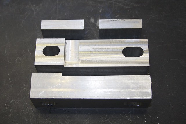
and with a plate across the parallels I can mill the angle blocks. I made two sets; one for clamping directly to the milling table, with a 1/8" step and holes, and a smaller pair for use in the vise:


Now we can put  those angle blocks to work! I started with the base end pieces. Here's one on its side in the vise, with the base of the part clamped against the angle blocks (on the right side). A bit of bar on the left ensures that the part's angle is controlled by the angle blocks and not the vise jaws.


Now I'm ready to mill the base radius with a 3/16" ball end mill, in three passes:


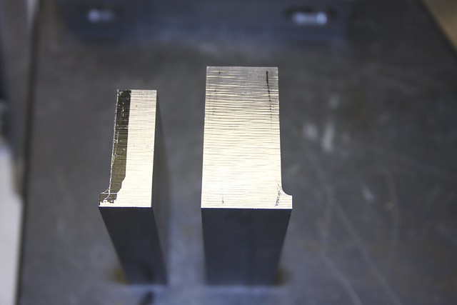
and the rest of the material was milled off with a 1/2" cutter. Do that a couple of times and we have our end pieces:


Now the long base sides pose a bit more of a challenge, given their length.

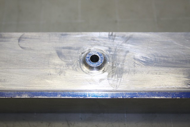
Before going any further, I located, drilled and reamed a hole corresponding to the main crank location (this will be milled away to create the bearing slot later, but it's useful now as a datum, and to keep the parts aligned). I also drilled for the valve adjustment lever. Now I can keep the parts together for the next few operations.

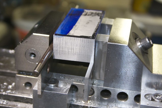
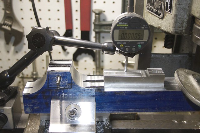
I have to mill the ends of the side pieces from the top; there's no way I have enough headroom to do what I did for the end pieces above. So the sides are held in the vise, and tilted to get the casting angle. I'm using one of my angle blocks and an indicator to get the angle right:


I took off the bulk of the material with a rougher, then cleaned up with a 1/2" end mill, leaving enough material to form the radius later:


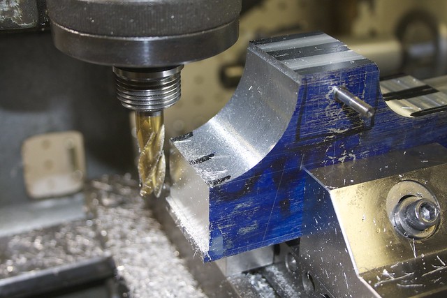
Finally I used the 3/16" ball end mill to do the profile. My end mill was only just long enough, and on one end I was a bad person and put the end mill in a chuck, because it was the only way I could get enough clearance to make the cut. But taking light cuts there were no mishaps.

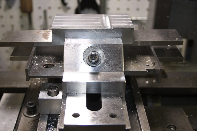
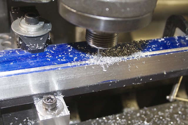
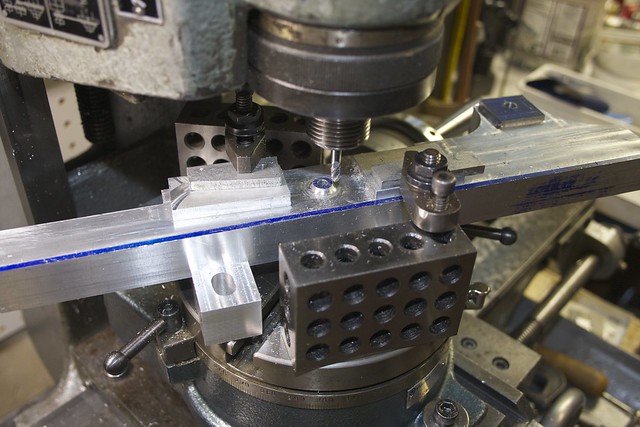
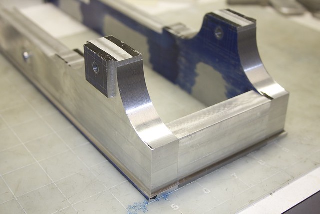
Now it's time to do the long sides! We're really pushing the limits of my machine here:


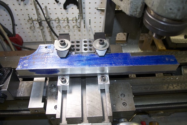
The stepped angle blocks earn their keep, and a bit of hardware store hot-roll flat bar adds some mass and stiffness under the part. I used an indicator to carefully tram in the part, since any error here would be very obvious over this length. It's not obvious from the photo, but the angle blocks are tilting the part such that the front edge is lower than the back.

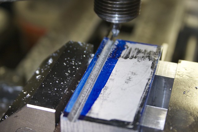
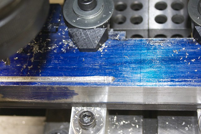
Again the first step is the ball-end mill, under slow power feed doing three passes:


On the first pass I was feeding too fast, and the cutter clogged and broke a flute, which was obvious from the change in noise and the uneven cut:


Luckily it's a two-ended cutter, so I flipped it around and carried on a bit more gingerly!

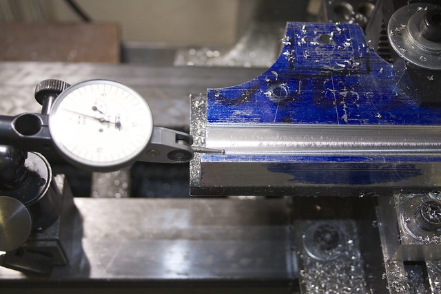
The bulk of the material was removed with a 1/2" cutter again. Here I've done one pass close to final depth, and I'm using an indicator to measure the difference in depth between the profiled channel and the new cut, so I know how far to drop the cutter to get things to match:


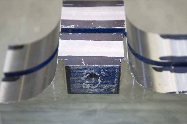
There is a quarter-round profile around the bearings that I'm going to try to machine from the bulk material, so we leave the bearing area alone:


After completing one side, I'm pleased to see that I'm spot-on depth-wise at the top of the part with my marking-out. The power of maths!  :whoohoo:


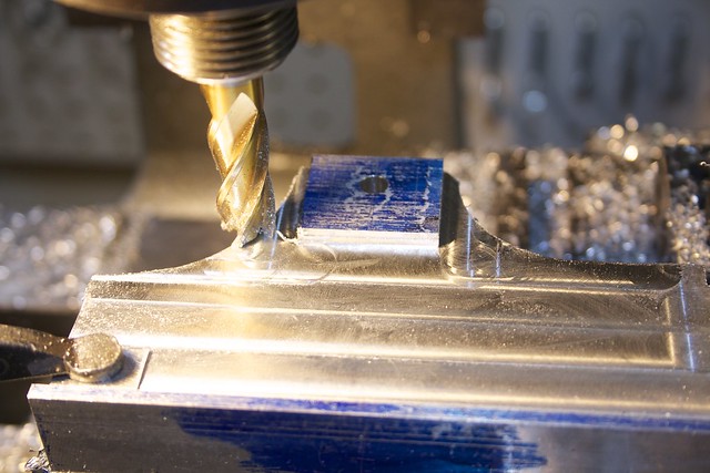
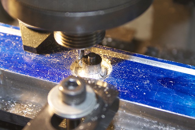
The second side has a boss for the valve lever, which I scoop out freehand with the ball-end mill and a filing button (if the button starts spinning, back off!):


and after taking off the rest of the material on this face, I finish off this boss on the rotary table:


which requires doing four separate cuts since I can't rotate the table all the way around with this long part!  :wallbang:

The results aren't bad, though:


but I might end up re-doing this profile with a smaller radius later.

So here's what we end up with:


Next is removing material from the insides of the base sides!

I'm also a bit unsure how to do the top plates. It would be sensible to use steel for stability, but there are quite a few projections (oil wells) around the crosshead slides and other bosses that would mean a lot of material to mill away, so I'll probably use Al.  :thinking:

Simon

Offline Jasonb

  • Full Member
  • *****
  • Posts: 9493
  • Surrey, UK
Re: Muncaster's Joys Valve Engine
« Reply #27 on: October 13, 2013, 07:22:52 AM »
Sides look good. For the projections what about soldering or sticking them to a thinner plate rather than cut from solid.

Offline NickG

  • Global Moderator
  • Full Member
  • *****
  • Posts: 1430
Re: Muncaster's Joys Valve Engine
« Reply #28 on: October 14, 2013, 06:58:06 PM »
Great start Simon, nice to see this materialising after seeing your CAD design. I'll definitely be following.

Offline smfr

  • Full Member
  • ****
  • Posts: 1203
  • San Francisco Bay Area, California
Re: Muncaster's Joys Valve Engine
« Reply #29 on: October 15, 2013, 05:57:15 AM »
Hmm, I'm confused.  :insane:  I'm modelling the crosshead, as shown in the attachment, and looking at that cotter. I can't figure out how the cotter and related nuts work. Shouldn't the wedge be reversed, so that tightening pulls the wedge up? Or is the hole in the top face of the crosshead threaded, and tightening is pushing the wedge down?

[Edit: it must be a threaded hole, right? There's no way to get a cotter fixed on a threaded rod in there]

Simon


SimplePortal 2.3.5 © 2008-2012, SimplePortal