How is this project coming along? I think I see how the magnets and stator pole pairs work. At the point shown in your sketch, the N pole 1 is aligned with stator pole 1, S pole 4 with stator 5, N7 with stator 9, and S10 with stator 14, so you will get a voltage peak on the black winding (A) at this point (0 degrees).
Then there will be N3, S6, N9, S12 for a peak on the green winding (B).
Then S2, N5, S8, N11 for a peak on the blue winding (C).
Then N1, S4, N7, S10 for a peak on the red winding (D)
That would be 1/16 of a revolution, or 22.5 degrees. At this point the next sequence would be:
S12, N3, S6, N9 for a reverse peak on winding A. If I have understood this correctly, there will be four positive transitions followed by four negative transitions for each 1/4 turn, and four complete cycles per revolution.
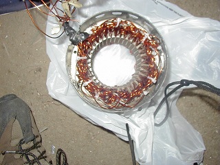
I don't have much experience with generators, but with induction motors the winding pattern is much different, and usually there is overlap with belts that span at least three stator pole pieces, at least for three phase motors. The stators I have worked with have had 24 and 36 slots, and the maximum number of pole (pairs) would be 8 or 12. I rewound a couple of single phase motors for three phase, with much heavier wire, for a voltage of about 8 VAC, and then I used a VFD and step-down transformer to apply 240 Hz, at which point the 12 pole 600 RPM motor spun at 2400 RPM. It looked like this:
I actually made my own crude solid state three phase drive and was able to spin the motor using a 12V battery. But the MOSFETs were not properly rated and they released their "magic smoke".


