I've had a couple of questions after I mentioned a slip eccentric in another thread, so I'll add a bit more detail here.
Background:A slip eccentric is one of the easiest ways of making just about any slide or piston valve steam engine that uses a single eccentric to drive the valve with reversible.
It's not often mentioned - most likely as it was rarely (if ever) used on full size stationary steam engines. I found the first reference to slip eccentrics while browsing around garden railway forums; it's often used on simple 1:16 locomotives.
There are MUCH better valve gears around for making engines reversible; the slip eccentric is not adjustable like the others, so can not be used to control things like varying steam cut-off. To reverse the direction on an engine using a slip eccentric, it is also necessary to turn the flywheel of the engine manually in the direction one wants it to go for at least 1/2 a turn, or in the case of a locomotive, to push the loco a short distance in the direction one wants it to run.
So in essence it's a bit of a gimmick that can be added to small engines to make them more interesting, as a simple way to study valve operation, and lastly it's just a good little exercise in machining.
Operation:A single fixed eccentric is normally fitted so that it is rotated 90
o respective to the crank. The direction it is rotated relative to the crank determines the direction the engine will run in; in order to change the running direction of an engine with a fixed eccentric, the eccentric must be loosened from the crank shaft, turned through 180
o and fastened again. The slip eccentric allows this 180
o turn to happen without loosening the eccentric from the crank shaft.
In most basic form, it is made of two parts; one part is fastened to the crank shaft, and the other bit actually driving the eccentric rod is loose to turn, and restricted to the needed 180
o movement.
Here's a simple one I made a while ago for my Elmer's #32 engine:
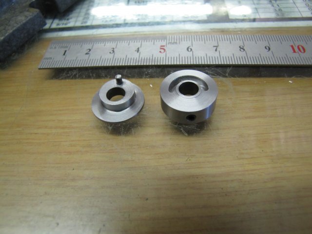
The part on the right is made to be fixed to the crankshaft with the grub screw that's visible at the bottom. It has a 180
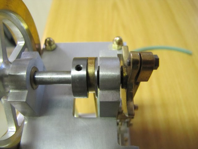
o groove milled in it. The part on the left is made to be a loose running fit on the crankshaft, and the pin mounted in it engages in the groove. As you can see, this makes the "eccentric" bit; the flange left on it is to retain the eccentric strap on it from one side, and once assembled together on the crank shaft, the eccentric strap is held in place between the two parts. Of course, some means of keeping the "loose" bit of the eccentric in position is also needed; in the following photo I simply used the bearing bush in the bearing column to keep the loose bit in place between the bush and the fixed part of the eccentric:
A short video of the eccentric in action; you can see that I manually turn the flywheel in the direction I want the engine to run - if you watch closely you will see how the eccentric "slips" relative to the crankshaft:
I just videoed this on the kitchen counter, so please excuse the parrot chirping up in the background and any huffing and puffing; I just ran the engine on breath-power.
Some "Gotchas" to look out for if you want to make a slip eccentric:Successful operation of the slip eccentric depends on a little friction in the valve train to make it operate, and as little friction as possible in the eccentric itself. If there's more friction in the eccentric assembly than in the rest of the valve train, it won't operate, as it won't be able to "slip"
If you make a slip eccentric, and you can't get the engine to run, turn the fixed part of the assembly through 180
o on the shaft. The eccentric's slip and lock directions are directional; if the engine wants to start to run and the "slip" is in the wrong direction, it will just immediately want to reverse direction again. Like I mentioned earlier, it's a good way to study valve gear operation on simple engines to learn how they work...
There are many different ways to make slip eccentrics; this was just one way that I happened to have on-hand to show. If you want to fit a slip eccentric to an existing design with a fixed eccentric, the slip eccentric must be built with exactly the same offset as for the fixed eccentric.
Multi-cylinder engines with separate eccentrics for each valve can also be fitted with slip eccentrics; simply replace each fixed eccentric with the equivalent slip eccentric.
I intentionally kept this write-up as simple as possible; there are other factors in an engine's operation that can to some extent be influenced by changing the design of the eccentric a bit, but that's a long story

Hopefully this is of some use.
Kind regards, Arnold


