Author Topic: Spraymist Ramblings  (Read 10795 times)

Bogstandard

  • Guest
Spraymist Ramblings
« on: April 27, 2013, 01:25:39 AM »
I was asked by another member to show this on here.

This is NOT a be all and end all posting, but an insight into what I did to get away from flood coolant.

What I eventually ended up with was a unit that worked perfectly for me, and even though I didn't eventually get to finish building ones for all my machines (my private life collapsed around me), this prototype, as shown, is still up and running perfectly, with no airborne mist problems usually associated with this type of unit.

Just a reminder, what I show is how I do things, other people may have other ways to achieve the same results.

So, away we go.

########################################################################

I have been using flood coolant for many years, but since my new machines were installed, I have only ever used it on my mill, never on the lathe. This project, if it works, will get me away from flood coolant altogether, and I will make a spraymist unit for the four machines that require it, lathe, mill, surface grinder and power hacksaw.
Having read both good and bad reports about spraymist, I have decided that good far outweighs the bad, and with a little redesign of a cheapo unit, I should be able to eliminate some of the bad faults.

I think the main complaint is that the mist gets airborne, and soon fills up the shop. I hope to get my systems using very small quantities of air and only tiny amounts of coolant. To such an extent, it will be a total loss system, just a quick wipe up in the area you are working in after you have finished.

Please remember, this is experimentation on my part, and really the results won't be known for a fair while, as I play about with different size and design of nozzle. But what I will be doing first off, should get me a basic working system.

Over the last few months, I have been gathering together all the bits to make the required number (and some). The main parts are the Locline type type coolant pipes. They can be as cheap or as expensive as you want to make them, but I have found that, the really cheap stuff is just that, and only really suitable for fitting into a fixed position, like on the power hacksaw.


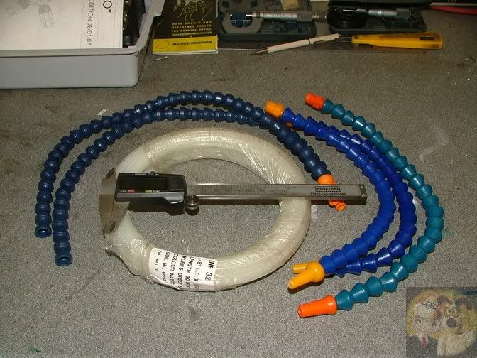
Earlier this year a friend brought me a unit back from the US, a nice cheapo job from LMS.

http://littlemachineshop.com/products/product_view.php?ProductID=2725&category=

Cheap and cheerful, and I suppose it must work, otherwise they wouldn't be for sale.

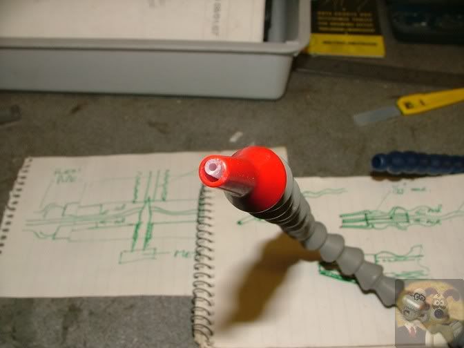
The main problem that I can recognise instantly is the way the nozzle works, and it is this area that I will concentrate my main effort on.
It works on the venturi principle, where air is speeded up as it goes past the pipe end, and when it hits the larger opening of atmosphere, the pressure drops (lower pressure than surrounding air, it could be described as a partial vacuum, if such a thing existed) and the coolant is sucked up the pipe and mixed with the jet of air. Hence it is spraying a mist of coolant.
I will be attempting to reduce the amount of coolant flowing and trying to get a more efficient venturi effect.
There is no coolant loose in the Locline at all, that is reserved for pressurised air, the small tube you see actually runs all the way back to the coolant tank.


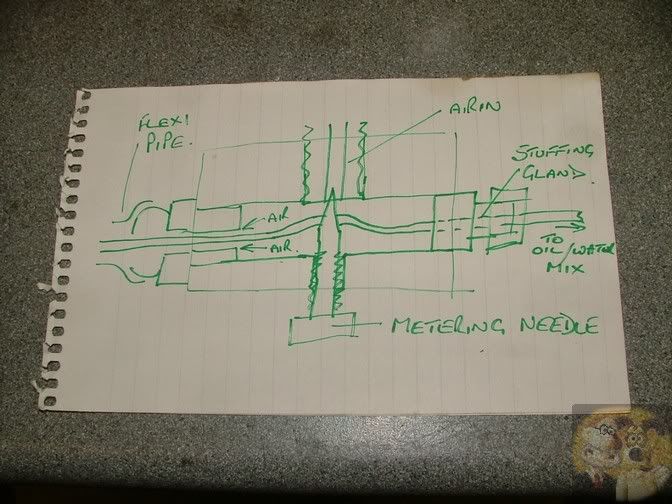
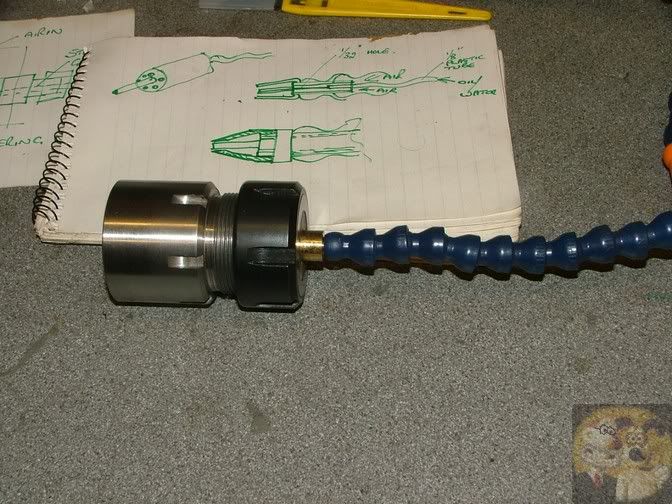
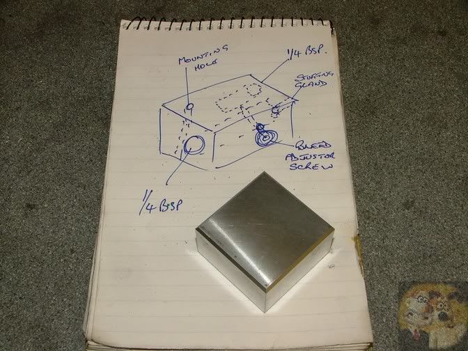
I scribbled up a bit of a design for a more efficient nozzle, and this will evolve as it is made.


This is a rough sketch of the commercial unit air block, with a slight addition of my own of the stuffing gland, to assist in stopping air leakage, and also hold the inner pipe so that it cannot be pulled out easily.


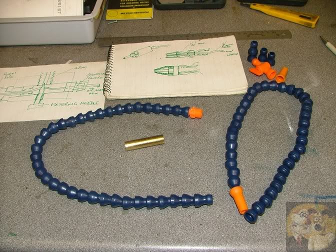
So now to get on my way. I will be using the pipe on the left, and as you can see, the orange nozzle has already been discarded, I will be making my own up to fit.
Because there is actually no loose liquid inside the big tube, I am hoping that friction or Loctited joints will be satisfactory, plus I am expecting to use very low pressure and volumes of air, maybe around 20 to 30 psi, and micro litres in volume.


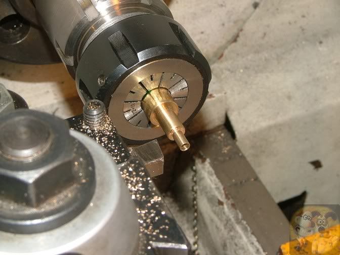
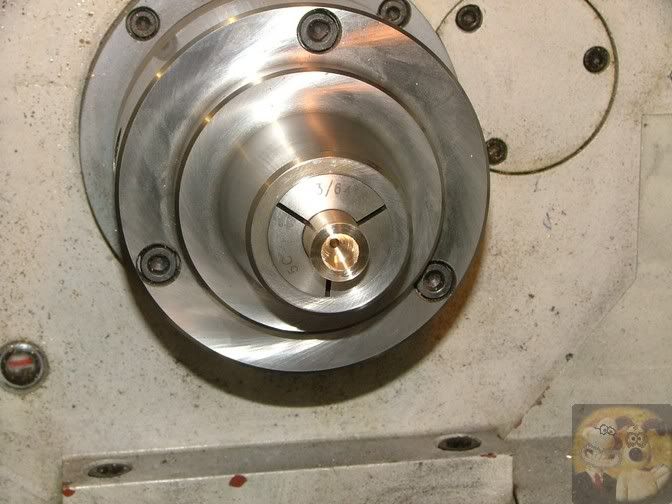
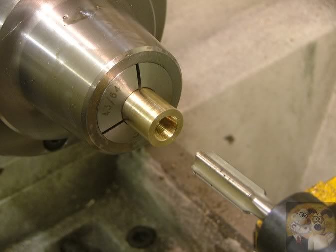
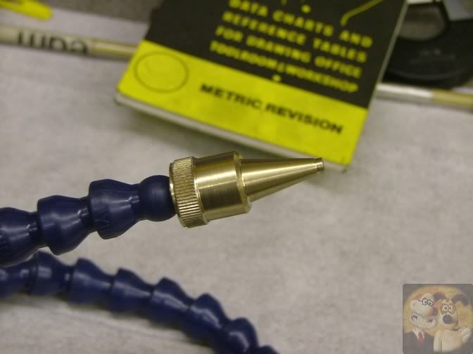
The piece of brass was mounted up in the lathe and the end shaped up.
I will just explain what the bits are for.
The hole in the end goes all the way thru the nozzle, and is a very tight fit for the small pipe. The pipe will be forced up the end by say 1/2" and loctited in. The middle diameter is a friction fit into the end of the outer plastic tube.
I now need to drill air transfer ports to get the pressurised air from this side to the other.


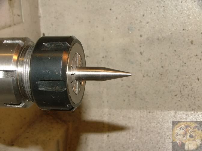
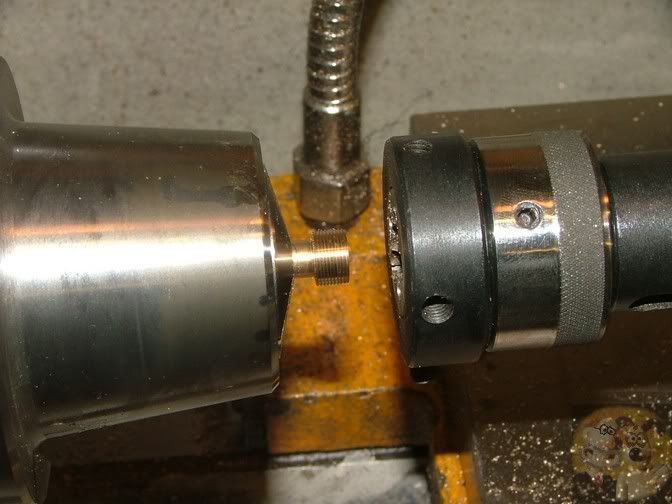
This shows how it fits into the end of the Locline.


Set in the RT, I carefully drilled down on the land between the medium spigot and the small one. I drilled 6 off by 1mm holes. I am not worried that they stay straight, as long as they reach the other end without breaking into the central hole or the outside of the central spigot.


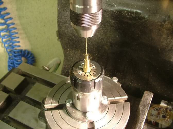
The six transfer holes drilled, no breakouts but they were a bit higgledy-piggledy on the other side. No concerns over that, the holes are thru and that is all that matters.


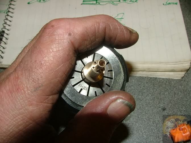
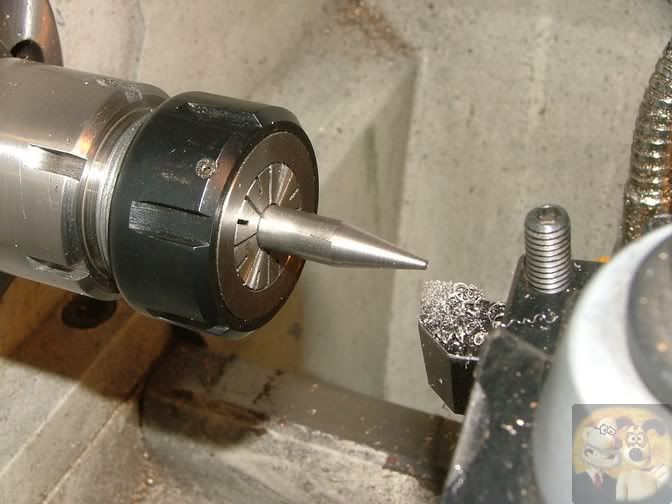
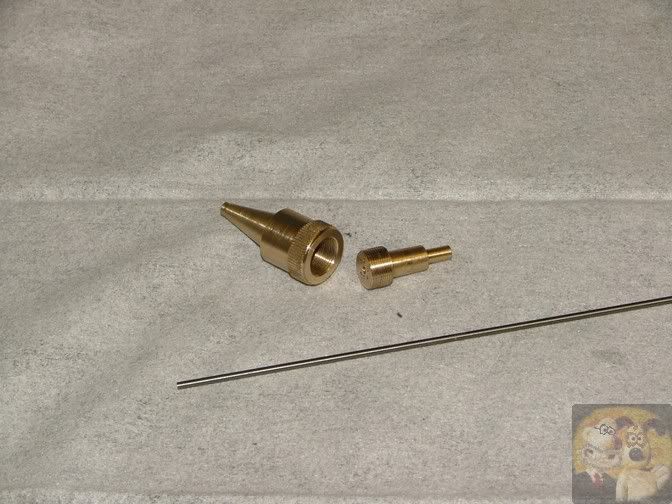
The other end of the nozzle was cleaned up ready to accept a fine bore tube.
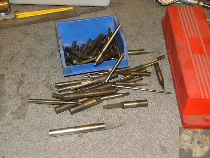
The ones shown here are actually tungsten tubes off a spark eroding machine, the big one just behind the nozzle is about 2mm diameter with a 1mm hole up the centre. I will be starting off with a fairly small one, and experimenting with larger ones if I can't get the flow I require.
Once things work out just fine, I can turn the whole nozzles up out of brass, and drill the correct hole in the middle.


This bit might be a little more interesting, because it shows how to make a most underrated tool, the lowly D-bit.

Just to explain a little, a venturi nozzle can be very difficult to design and make, because there are so many variables, and I couldn't even start to be anything but a total novice in the design of one. But there are a couple of basic figures that I know will give me a design that works. These are shown in the C-o-C.
I will be chopping off the front cone part, and it should work well enough to give me a usable spray nozzle.


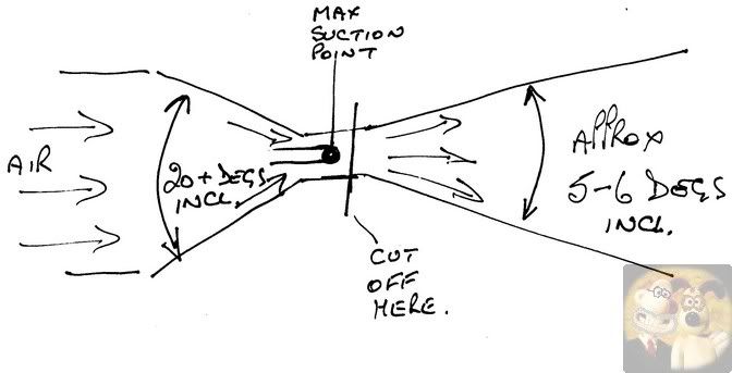
I want to make the back cone, and at this time I will make it adjustable, so I can find the optimum position for the inner nozzle itself.

But how to cut an internal taper as small as I want it? A boring bar is out of the question as it would have to be so fine, it would be almost guaranteed to break. I could get a reamer made to the angle I want, but it would cost lots of pennies. The answer is a D-bit, and if well made, is just as accurate as a commercially made reamer.
I am going to show you how I make one to continue with this job.

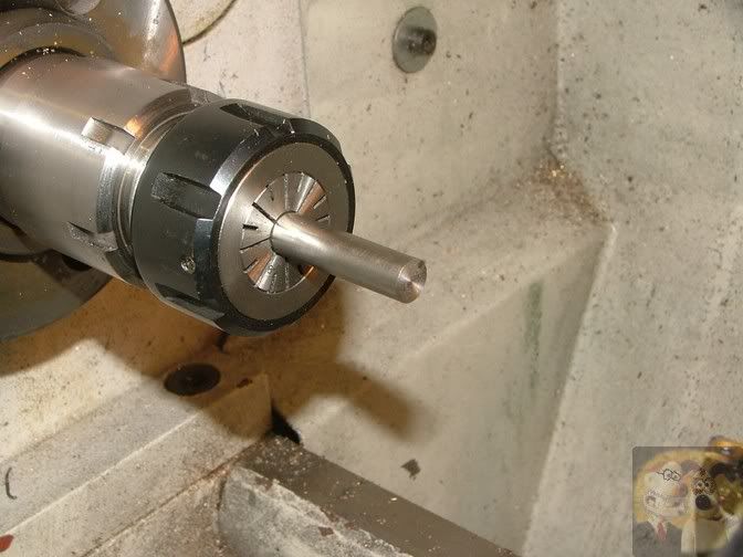
Mounted up a piece of silver steel (drill rod), and faced off the end.


Kicked the topslide (compound) over by half the angle required, in this case 11 degrees.


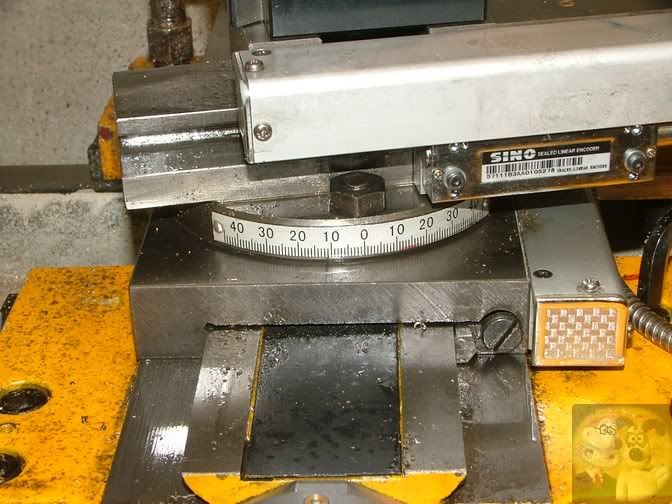
Then using the topslide, the taper was being cut.


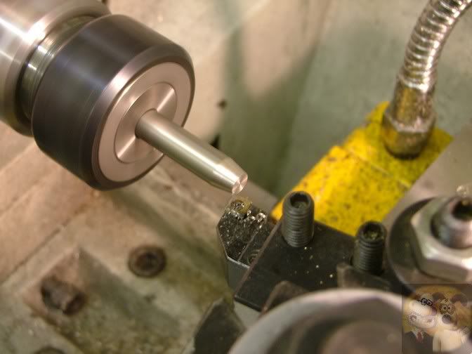
The taper was finished when the small end was at about 2mm. I will be drilling a 3mm hole thru the nozzle material, so this D-bit will not require a cutting edge putting onto the very end.


The machining marks were gently removed with fine emery.


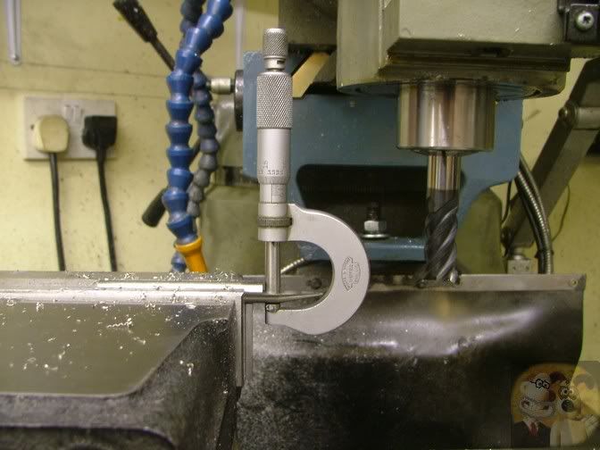
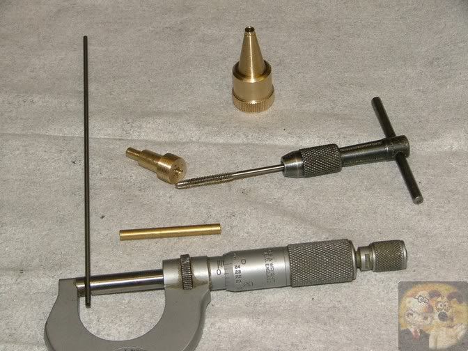
The bar was accurately measured up (this was 3/8" or 0.375"). Then it was divided by 2 and the figure rounded up. It was at this stage I changed my normal making practice. I would harden at this stage and grind the end down on my surface grinder. But because most people don't own such a machine, I am going to do it the normal way.


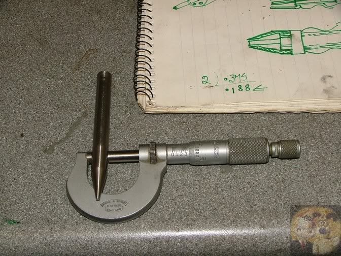
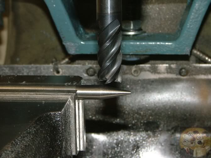
Mounted up perfectly level in the milling vice, the bar is reduced down by not quite half it's diameter. One or two thou larger is ideal.


Mine measured up when finished at 0.1885", one thou over half size.


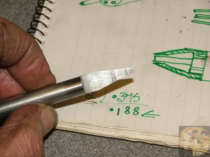
This is what it looked like close up. The machining marks are only tenths of a thou deep, so no worries over those. I would forget about deburring, as you can easily take too much off the edges and prevent it being sharpened.


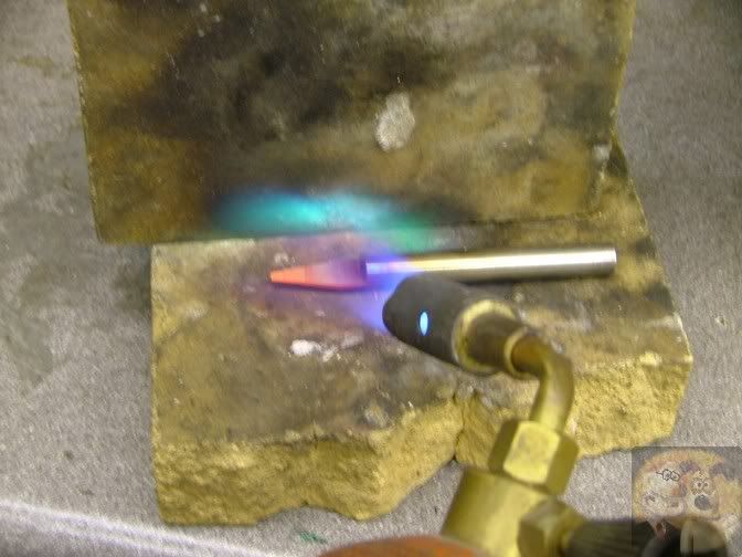
It was now time to get things warmed up and hardened.
Just the part that was machined was heated up to cherry red, and held there for a minute or two, then it was quickly quenched in water.
This should make the tool as hard as glass. I don't bother tempering the tool, that is just a personal thing.


The machined face is then gently smoothed down on a smooth oiled stone until the machine marks are gone. You should end up with edges as sharp as a razor.


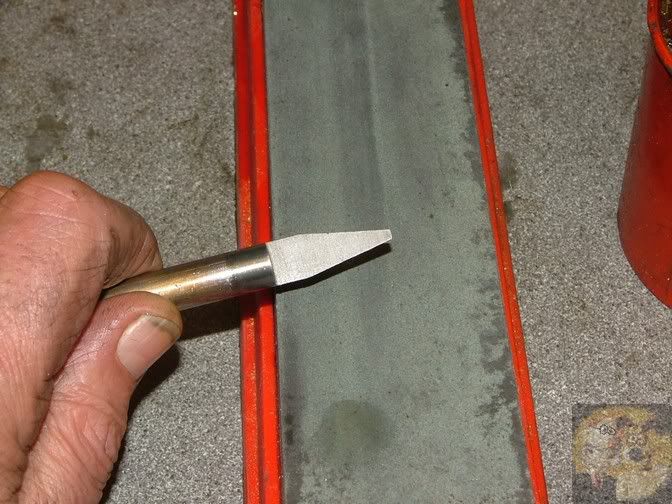
You tend to hoard the good and more useful ones that you make. Just in case.


So that is the D-bit made.


I have almost done the inside bit, but before going any further the outside nozzle needs to be made.
So a bit of brass bar about 2" long was chucked up. A 3mm hole was drilled to a depth of about 40mm, then it was followed down by a 10.5mm hole to a depth of 12.5mm.


Time to break out the D-bit I made, in the hope that it works (not really, if you make them to the basic dimensions I have shown, they are almost guaranteed to get the job done)
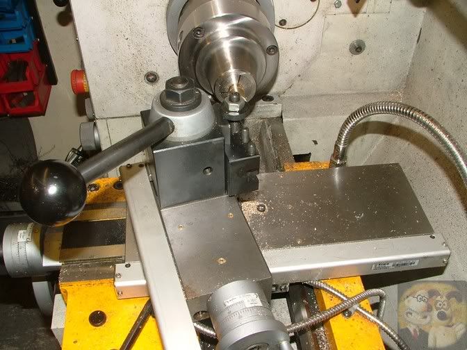
I had marked it up so that it would penetrate to about 35mm. The lathe was set to it's slowest speed of 65 RPM.


It is then a matter of pecking into the hole and clearing very often. As you can see, it is doing a lovely job of scraping the shape out of the inside. As I have said before, if you can make a good one, they can be used instead of a reamer. But that 1 or 2 thou thicker than centre and razor sharp edges are critical.


To allow me to get super fine adjustment for the nozzle, I threaded the inside bit with 7/16ths by 40 TPI. This is the same pitch as an imperial micrometer uses, so one full turn of the nozzle will move it backwards or forwards by 0.025" (0.62mm).


The nozzle was turned around in the chuck, and the end faced away until there was 3mm straight portion left of the previously drilled 3mm hole. After that it started to open out into the taper I had cut with the D-bit.
The topslide was then set over by 11 degrees, the same as the internal taper.


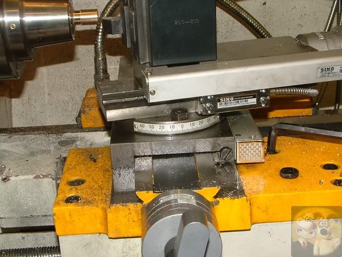
This shot from the top is when I was cutting the outside taper using the topslide.


This is what it ended up like, a 3mm straight bit at the nose and then the taper. This should be the same as the profile on the inside.
I did a little more work on the outside, but nothing that really deserves a mention.


So now onto the other bit of the nozzle. The end was faced up and an external thread the same as the other was cut onto it.


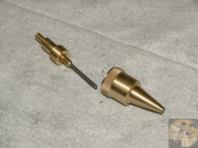
The two mating parts. Now I just need to get the tube into the inside bit.


The inside part was tapped out, and to cut a long story short, the bit of brass was drilled thru with the same diameter as the tube and a thread cut to match the small thread just cut was put onto it.


After Loctiting the tube into the holder, the assembly was screwed into the inside part. If necessary, different sizes of tube with their holder can be made up and screwed into position.


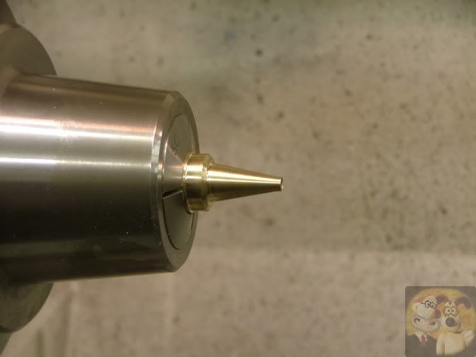
The business end of the nozzle.

Do ya feel lucky, punk!!


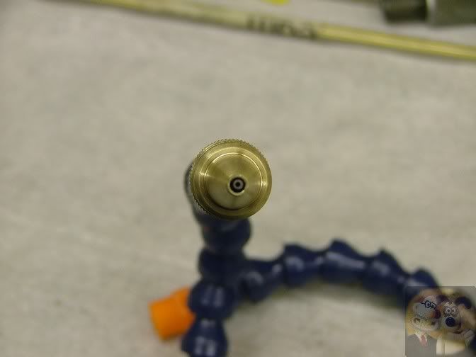
This is how it will fit onto the Locline.
By doing it this way, I have about 10mm adjustment of the outer nozzle in relation to the inner one.


You might think I am going to a lot of trouble making this nozzle.

By doing it this way, with adjustments to the critical positions and sizes, I should be able to find the ideal settings that I want, and be able to replicate an easier made nozzle for the four units I require. Plus I should also be able to do a sketch so that people can make their own if they want. So all this work will not be wasted, it is called R&D.


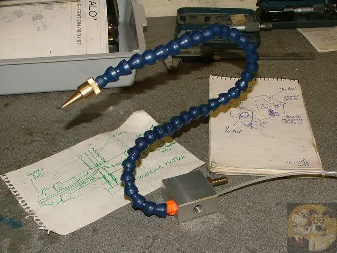
As usual I did a quickie sketch to remind me what I want to end up with and also a few dimensions if I need it. I had already prepared a little block of ali.


The holes that were required were drilled and if needed tapped.
This pic shows what the assembled unit will look like. I have still to make the stuffing gland to seal where the little pipe comes out of the back, and the metering needle to control the air flow.


#####################################################################

I know that this is a sudden end to the post, but to follow on.

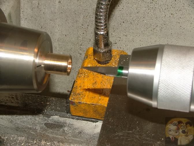
I finished the unit off to what my sketches showed, and the air pressure was set so that fluid was only just being lifted from the tank (you can see the fluid moving through the pipe), then the nozzle was adjusted back/fwds to give a very small misting effect.
I set it up by spraying onto my thumbnail, until I saw just a tiny amount of coolant oil on there. It was then a matter of balancing out slightly the air pressure and nozzle position until that whenever the unit was turned on, the same misting quality was there each time.

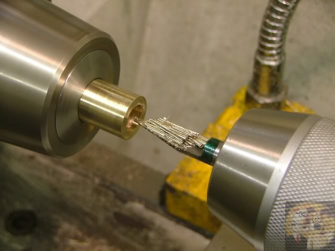
I found that by pointing this at the cutting area, the chips were softly blown away and there was a very fine film of oil on the cutting tip/job. The tool tip, and job, remained cool to the touch, because of the small jet of air.

No airborne mist was seen, even after an hours use, and only a tiny amount of fluid to be wiped away off the bed with a cloth.
In fact, the nearly full, one pint bottle of fluid, used every time there was some cutting needing coolant, lasted for nearly a year.

So, as built, a perfect result for me.

My personal view, of people who put these units down because of heavy misting in their shops, is that they are not adjusted correctly, and if time is taken, they can certainly take the place of flood coolant in almost all situations.

I hope that this bit of writing and pictures may give someone the inspiration to have a go at making something like this.


John

Offline Steamer5

  • Global Moderator
  • Full Member
  • *****
  • Posts: 1272
  • The "Naki" New Zealand
Re: Spraymist Ramblings
« Reply #1 on: April 27, 2013, 03:37:59 AM »
Hi John,
 Many thanks for taking the time to post this. LOTS of great tips on the "how to" & then ending up with a very useful tool at the end, and yet another on the list of things to make!

Cheers Kerrin
Get excited and make something!

Offline Pete49

  • Full Member
  • ****
  • Posts: 736
  • top of the gulf SA, Gateway to the Flinders Ranges
Re: Spraymist Ramblings
« Reply #2 on: April 27, 2013, 06:20:30 AM »
Thanks for reposting John. Now to try and do it justice
Pete
I used to have a friend.....but the rope broke and he ran away :(....Good news everybody I have another friend...I used chain this time :)

Offline Bezalel

  • Full Member
  • ****
  • Posts: 376
  • - Skype:Bezalel2000
Re: Spraymist Ramblings
« Reply #3 on: April 27, 2013, 07:32:07 AM »
Thanks John
 
That is just Sooooo cool  8)  Dude!
 
(Pareden the double entendre)
 
Bez
Queensland - wet one day, humid the next

Bogstandard

  • Guest
Re: Spraymist Ramblings
« Reply #4 on: April 27, 2013, 08:38:32 AM »
I am open to questions on this one because of the incomplete post, and because I have also used it a lot.

John

Offline ColH

  • Full Member
  • ****
  • Posts: 55
  • Geelong, Victoria, Australia
Re: Spraymist Ramblings
« Reply #5 on: April 27, 2013, 12:38:54 PM »
Hi John thanks for posting this as it should make working a lot cleaner.
Did you end up using the original coolant tube (1mm id tungsten)? 
What distance back from the nozzle tip was the front of the coolant tube? 
Do you think it is necessary to retain the adjustment functionality or can you provide a drawing of the settings that work?
What impact does the the length of the coolant pipe have on the air pressure/flow required to draw the coolant?
What type of coolant do you use?
Thanks again for posting
Col
ColH

Offline Tater

  • Full Member
  • ****
  • Posts: 21
  • East Village, New York City
Re: Spraymist Ramblings
« Reply #6 on: April 27, 2013, 02:01:07 PM »
Interesting!  I have the small Kool Mist system and it works well, though the flow of coolant is more than I would like - I feel the mist should be finer - more efficient.  I think the difference is in the nozzle.   OK - after looking into things - of course the Kool Mist *is* a Venturi design! :Doh: It's just a different sort of design.

Here's a photo of the Kool Mist nozzle:


I've thought about making my own nozzle but never considered anything as sophisticated as a Venturi design - if you ever make a proper drawing I'd certainly do it!  :praise2:

The other thing I notice is that you suggest a low pressure - 20-30psi, whereas the Kool Mist is recommended to run at 90psi or more?  Is the low pressure enabled by the efficiency of the Venturi design?  Perhaps this might cut into the sale, (purchase!) of Kool Mist coolant!  :thinking:

Anyway - Very nice design and execution John - worth the price of admission just to see your toolmaking!  :cheers:

Thomas
« Last Edit: April 27, 2013, 04:42:35 PM by Tater »

Offline arnoldb

  • Administrator
  • Full Member
  • *****
  • Posts: 1341
  • Windhoek, Namibia
Re: Spraymist Ramblings
« Reply #7 on: April 27, 2013, 09:09:44 PM »
Thank you very much for re-posting this John. 

A question if you don't mind:  Is there some form of special coolant for the spray-mist system, or will a synthetic water-soluble cutting oil work with it ?

Kind regards, Arnold
Building an engine takes Patience, Planning, Preparation and Machining.
Procrastination is nearly the same, but it precludes machining.
Thus, an engine will only be built once the procrastination stops and the machining begins!

Bogstandard

  • Guest
Re: Spraymist Ramblings
« Reply #8 on: April 28, 2013, 10:34:53 AM »
Col,

As you can see from the picture of the end view of the nozzle, the hole in the brass nozzle is 3mm, the tube is about 1.5 mm diameter and the hole 0.75mm. Without stripping it down, I can't give you exact figures.
On my final settings, the tip of the tube is protruding a tiny amount, maybe 0.2mm, from the end of the brass nozzle.
Personally, when I get to make my other ones, I will definitely leave the adjustment on there for the outer nozzle, as I think it is that which allows you to get the perfect position, but I will make the internal tip and everything associated with it out of brass by measuring up the one I have already made.
 
My coolant pipe, 1/8" OD, is about 5ft long from nozzle tip to tank bottom, with my bottle hanging on the back splash of the lathe. It is that length and height of the bottle that governs the amount of pressure required to draw the liquid. Basically, once the coolant is through to the tip (it can take a minute or so), siphoning does take place, and that must help in reducing the pressures required to get the fluid from tank to tip at all times. But one thing I have noticed, the siphoning effect is tiny, maybe one drop every couple of minutes, maybe due to the small internal diameter of the tip hole.
The bottom of the bottle during use is about level with the nozzle tip (which varies slightly in use because of what diameter bar is used) and when I have finished, I lift the nozzle above the level of liquid in the bottle to prevent further siphoning.

I use a coolant that a friend gets for me (100 to 1 mix with water), and it is designed primarily for surface grinding, but I find it works perfectly well for cutting metals as well. So I can see no reason why any other water/oil mixes shouldn't work just as well, as long as it is not too 'thick', otherwise you would need more pressure to 'lift it'.

Thomas,

The venturi I put on mine was what I had seen to work in previous experiments I had done in my place of work (again, lifting and spraying of a fluid), so I used those figures. As I said I'm no expert in that field, but it looks like I have got it almost, if not spot on for what I had to do this time.
I think that the high pressure use of commercial ones is what causes the main problems in our usually small workshops. Don't get me wrong, in my first setups, where I had the pressures higher, within a few minutes, my shop was full of mist and was causing me to cough uncontrollably. It is definitely the ability to get that pressure and flow down to low levels that allows my system to work. Maybe you could try to adjust yours down to much lower levels, to see if you can get roughly the same results I do.

Arnold,

I think your question has been answered.

I hope I have answered all your questions OK


John

Offline ColH

  • Full Member
  • ****
  • Posts: 55
  • Geelong, Victoria, Australia
Re: Spraymist Ramblings
« Reply #9 on: April 28, 2013, 11:20:25 AM »
Thanks John

Another project on the list for when I get my workshop see up again.

Col
ColH

Offline arnoldb

  • Administrator
  • Full Member
  • *****
  • Posts: 1341
  • Windhoek, Namibia
Re: Spraymist Ramblings
« Reply #10 on: April 28, 2013, 10:01:20 PM »
Quote
I think your question has been answered.

 :) Yes - Thank you John.

Kind regards, Arnold
Building an engine takes Patience, Planning, Preparation and Machining.
Procrastination is nearly the same, but it precludes machining.
Thus, an engine will only be built once the procrastination stops and the machining begins!

Offline Maryak

  • Rest In Peace
  • Full Member
  • *
  • Posts: 1818
  • Aldinga Beach South Australia
Re: Spraymist Ramblings
« Reply #11 on: April 29, 2013, 12:17:28 AM »

I use a coolant that a friend gets for me (100 to 1 mix with water), and it is designed primarily for surface grinding, but I find it works perfectly well for cutting metals as well. So I can see no reason why any other water/oil mixes shouldn't work just as well, as long as it is not too 'thick', otherwise you would need more pressure to 'lift it'.

Just a word of caution, soluble oils for grinders are of a different composition from the "standard" soluble oils used in lathes, mills etc. Synthetic solubles will probably mix down to 100:1 but the others run a fair chance of clogging fine spray mist nozzles.
 
Hope this helps

Best Regards
Bob
Если вы у Тетушки были яйца, она была бы Дядюшкой

Bogstandard

  • Guest
Re: Spraymist Ramblings
« Reply #12 on: April 29, 2013, 12:45:24 AM »
Thanks for that note Bob, I hadn't considered the viscosity that other people may use.

All I could suggest is suck it and see.
I can't see a problem with blocking though, as the nozzle is fairly large, but you must filter your coolant as it is added to the bottle. I actually have a ceramic fish tank air ball on the end of my pick up pipe to act as my filter, and it has never caused a problem.

That's what comes of having friends in high places and not ever having to pay for lubes any more. I must stock up before he retires.


John

Bogstandard

  • Guest
Re: Spraymist Ramblings
« Reply #13 on: April 29, 2013, 12:44:48 PM »
I found another picture of my unit last night, showing it completed and mounted to the lathe saddle


Two adjustments, one on the side of the block for air pressure and the nozzle itself.

It will be moved from this position eventually, as it is a little too far forwards. The next mod to be done to the lathe is to fit a T-slotted top to the cross slide, it will be repositioned further back when that happens.


John
« Last Edit: April 29, 2013, 12:53:11 PM by Bogstandard »

Offline Steamer5

  • Global Moderator
  • Full Member
  • *****
  • Posts: 1272
  • The "Naki" New Zealand
Re: Spraymist Ramblings
« Reply #14 on: February 09, 2016, 09:18:47 AM »
Hi all,
 Yep it's an old topic but I have a new twist!
A couple of months back Bogs posted on that "other site" that it appeared that somebody in China had taken up making a version of this mister. He purchased one to see how it went....so far no findings have been posted. Bogs pointed out that the liquid adjustment wasn't as easy as his, but once set shouldn't need further playing with.
As its on my " get to it one day" note this is a longer time than a " round tout" list! So I checked out eBay there are several sellers, there would appear to be 3 versions, 1 has ball valve control, figured this to be too coarse to control. 1 had what appeared to be needle valve controls on both air & liquid, Bogs recommends that you should only need one. So the last version was chosen, a single needle valve on the air. There are quite a few sellers of each type.
The cost, well it was coming up Xmas, so well one for the mill & one for the lathe & ah well a 3rd for dad....total cost $45 NZ delivered! Couldn't buy the parts for one for much less than that!
A couple of weeks ago time allowed a play. Got it hooked up liquid came out the desired end...well that's a start! Went to adjust the air flow....no way, didn't seem to matter what was tried.
Right off to google......starting to ramble, best stop ......soon......
I found that yes they are fitted with needle valves, HOWEVER there are two sorts! Both look the same, right angle with a tube fitting one side & 1/4 thread the other. The only difference is on the adjusting knob one has IN the other OUT. As fitted the mister has the OUT version, which is THE WRONG ONE, :Mad:  :cussing::cussing: it need the air in via the threaded end which is screwed into the mist as per the picture.
Well the eBay seller says if you have a problem they will fix it etc etc.......having swapped quite a few emails no fix has come yet! All very polite, have contacted there supplier etc, requested more info, a video & oh sorry our supplier hasn't gotten back to us yet....
I can drive down the road & buy replacement valves but it's more fun swapping electrons! :LittleDevil: I will end up most likely doing that but hay for now...........

So if any of you have gotten one, how have you found it? If you decide to get one, be aware of the valve issue!

Cheers Kerrin
Get excited and make something!

Offline gerritv

  • Full Member
  • ****
  • Posts: 760
  • St Catharines, ON
Re: Spraymist Ramblings
« Reply #15 on: February 09, 2016, 12:35:46 PM »
I too bought one like yours. Regardless of the label on top of the fitting, air will flow, or not, depending on how far out you screw the needle valve. It is just a label.

The bigger issue with this design is that although it looks on the outside like Bog's, inside is a different story altogether. The fluid hose goes straight through to the end of the lock-line. The air hose feeds to the outside perimeter at the lock-line end. The operation is by airflow creating suction on the fluid, and eventually dragging some out the end. Unlike Bog's design this happens at the end of the line.

A much improved design pressurizes the fluid, requiring considerably less air pressure and flow to arrive at the same spitting action.

My version has an extra air valve that will be used to supply high volume air directly to the periphery of the nozzle. I did find that the air flow valve is not needed, just the fluid one.
The original FogBuster patent has a good explanation: http://www.google.com/patents/US5390854
<a href="https://www.youtube.com/watch?v=x3AoB5a97BE" target="_blank">http://www.youtube.com/watch?v=x3AoB5a97BE</a>
« Last Edit: February 09, 2016, 12:42:31 PM by gerritv »
Don't confuse activity with progress

Offline Steamer5

  • Global Moderator
  • Full Member
  • *****
  • Posts: 1272
  • The "Naki" New Zealand
Re: Spraymist Ramblings
« Reply #16 on: February 10, 2016, 09:38:27 AM »
Hi Gerritv,
Yep agree the air comes out no problem, the issue is it comes out when the valve is shut, and there is little or no adjustment!
 The picture of my units, with the air plugged into the tubing push fitting, as you would think would be the air inlet, there is no control. IF you remove the valve & put the air in the threaded side then you get controlled air flowing OUT of the tube fitting from nothing to full flow!
When I googled these valves that's when I found that there are two types, as fitted to mine, with OUT on the knob, and the other which has IN. The info on them says that the OUT type controls the air flow out the tube fitting, the IN type controls the air flow out the threaded side.
Oh I checked out other sellers, surprising how similar the photos are, most appear to have used the same valve, sounds like you got the right valves on yours.
Hope this makes it clearer, sorry if I confused things in my last post, I know I'm getting a run around but 2 can play that game  :stir:
Agree that it's not like Bogs version, but if it  :hammerbash: me enough I'll build the Bogs end fitting or a fog buster version, thanks for the link.

Cheers Kerrin
Get excited and make something!


SimplePortal 2.3.5 © 2008-2012, SimplePortal