'
Here is the finish of this little project. I will have a video up a few hours later.
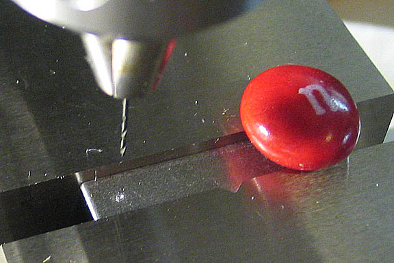
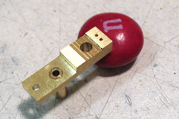
This piece will be a jig for drilling the port face holes, and the inlet hole in the cylinder. A .020" drill
is being use here, (1/2 mm). I'm doing this on the milling machine, as it has a very true spindle. The spindle on the
average drill press has too much runout to drill such a small hole, and the bit would be broken in a second.
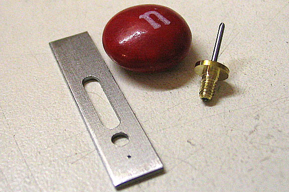
I also made up an alignment pin with a threaded end. These two jigs are used to accurately drill the ports
in the engine. The plate attaches to the crankshaft, and as the crank is rotated the plate will mimic the
arc traveled by the cylinder when the engine is running. The tiny hole will be used as a guide for drilling
the needed holes in the port face. The pin does the same thing for the hole that needs to go in the cylinder face.
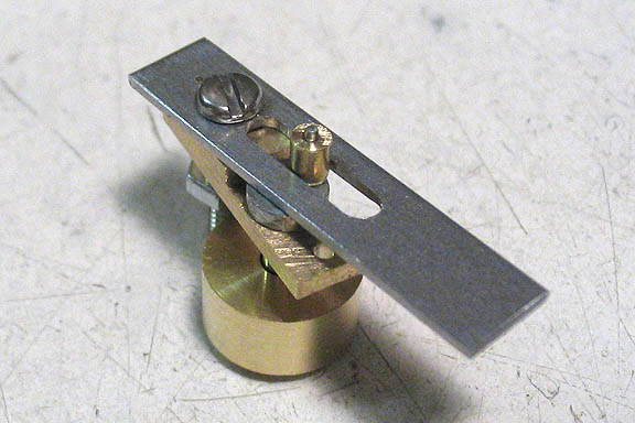
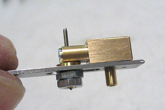
This is how the jig mounts to the port face of the engine. This may not be very interesting in itself, but
I wanted to show how one of these jigs works. A similarly made jig in larger scale will work perfectly for
aligning the steam ports for most any other oscillating engine.
If you were to need to fab a new port block for an engine, or say you soldered over the holes in an existing
port block, one of these can make your work in locating the holes not only easy, but very accurate.
What you need to know is the distance between the steam inlet in your cylinder and the pivot screw. Using a thin
piece of sheet steel, drill a hole in one end the same size as your port. Carefully measure from the center of
that hole and lay off the center of position for your pivot screw, and drill a hole the same size as that screw.
Finally, cut a slot in your jig piece. Take care to keep your two holes and the slot all in a straight line.
The length of the slot is not critical, as long as it allows you to mount the jig to your intended port face and
slip the slotted part over the crank pin on the crank shaft. Make the slot long enough to allow the flywheel/crank
to rotate through a full rotation. Also, make the slot just wide enough to let the crank pin enter it. It needs
to be a close fit.
When you get ready to drill your holes in the port face, mount the jig to the face using the pivot screw for
the cylinder, or another screw of the same size. In the pic above, I've used a hex head screw through the jig
and through the pivot hole on the engine port block.
The slot is placed over the crank pin as shown above. I had to make a small bushing for this one, as the jig is
used for two different drilling operations. The bushing is needed to remove any slop between the pin and the slot.
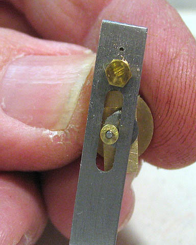
Finally, the crankshaft is rotated, watching the jig travel through its arc. At the extreme points of the arc
on each side of the crank pin rotation, the top tiny hole is used as a guide for drilling the ports.
Hope that made some sense. Easier to do than to say/type.
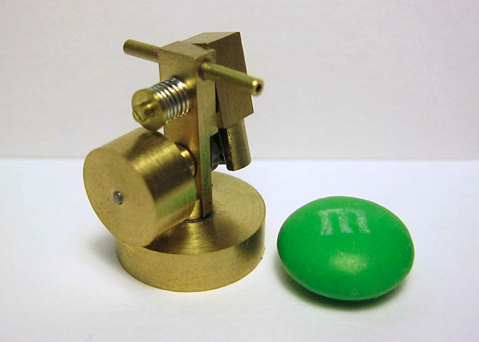
This pic shows how well the jig works. Holes perfectly spaced.
I use this kind of jig for most all of my wobbler engine builds. Just makes things easier, and gets it done
in one go.
The same jig is used to put the single hole in the cylinder, but this time with an additional pin jig that
holds the cylinder bore perfectly in line with the crankshaft bore.
Two more holes are drilled in the port block, one for the inlet and one for the exhaust, then all the parts
can be assembled.
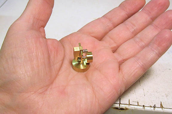
You can see how small the engine really is in this shot.
That's it, done.
Thank you all for your interest and nice comments. Video coming in a few hours.
DW


