Thanks Jo - Not to mention shoe-shopping

Got a Swedish clog thrown at me once for presenting a pair to an ex girlfriend after she tried on nearly all the shoes in the shop. I think my last statement before the wooden footwear headed my way was "Heck, they should be comfy and kick up just as much of a racket as the last twenty pairs of high heels you tried on"

Vince, thanks. I saw from your last post you decided against the facet milling - that's just fine. One of the freedoms of our hobby is that each and every one of us can do as we please in our shops. There's no right or wrong. Any way a part can be made safely is right

Thanks Bill
- I am enjoying it !
Not much done today - but I did manage to add the mini how-do-I that I promised to Stew earlier on.
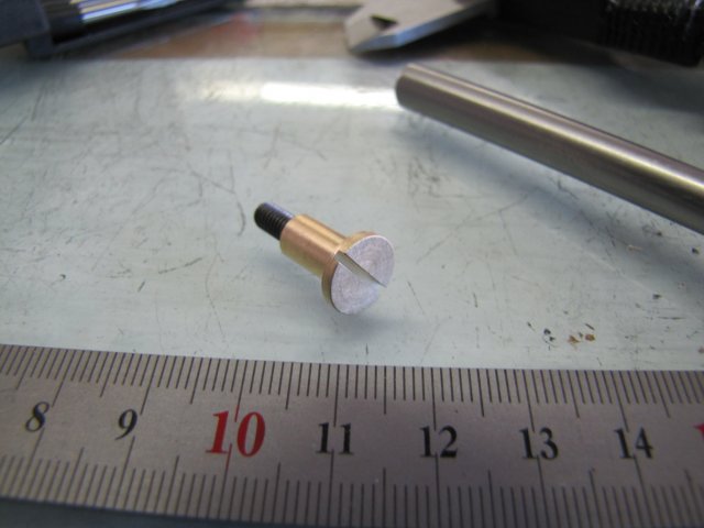
With due apologies to Bob Maryak, I deviated a bit from the plans for the crank pin. Rather than using steel for it, I decided to make it from a combination of steel and brass. The selection of materials is more "technically" correct rather than "hobby" correct; for hobby use all-steel would do just as well. And, anyway, I used what I have on hand. I could have made the entire crank pin from brass, but the M4 threaded section would carry quite a load while the engine is running. The flywheel will end up carrying quite a bit of momentum, and IMHO in the overall design, the crank pin will be the weakest spot.
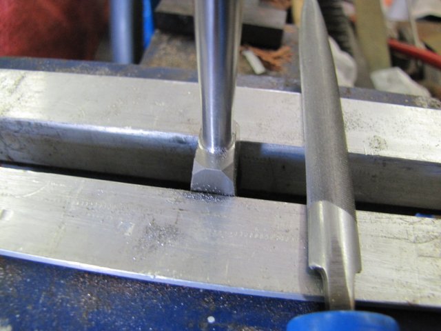
So I turned up the crank pin to dimensions, but rather than threading the end, I drilled, threaded and Loctited an M4 cap screw in there:
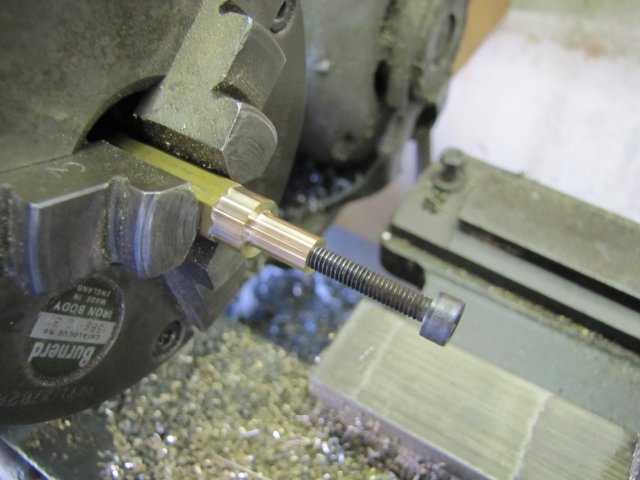
The cap screw was sawed off to length with a junior hacksaw, and the end cleaned up with a file.
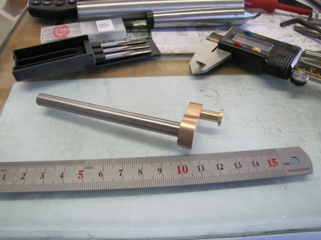
I promised Stew some photos of how I use my home-brew height gauge. There's a mini how-to (my way) coming up, but first off, for those that have not seen it yet, a year or two ago I built a height gauge that uses off the shelf unmodified cheap digital calipers - it can take both 150mm (6") and 200mm (8") calipers. I've only ever used it with the 150mm caliper, and, contrary to my original intentions of leaving the caliper stock standard, I've sawed off the "sticky outy depth gauge part" - that is the long thin section that is attached to the moveable head. For reference, this is what the tool looked like the day it was finished:

Unfortunately, some of the shiny bits picked up a lot of rust afterward

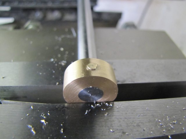
First off, I measured the diameter of the workpiece with a caliper -it measured out to 9.88mm
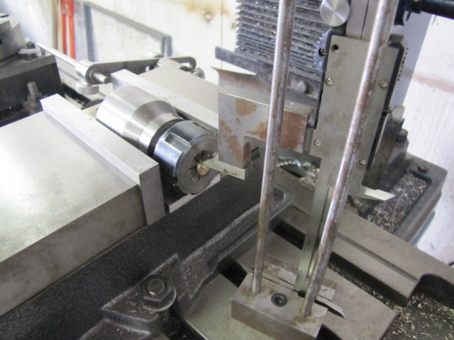
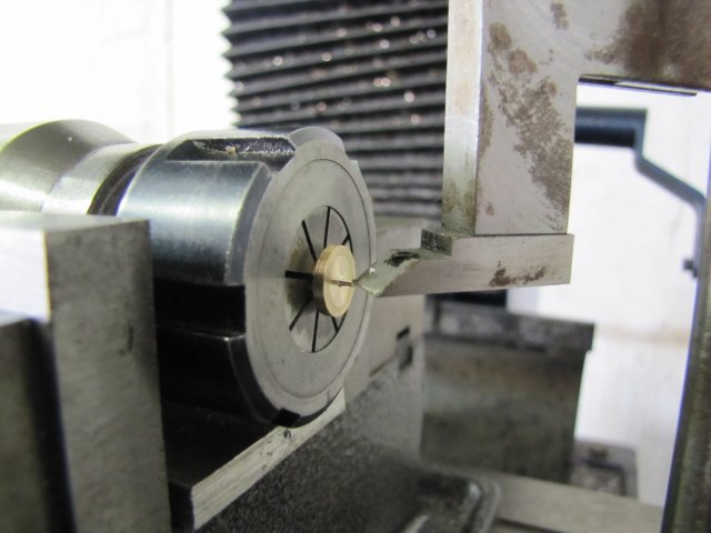
Then I chucked it up in the collet chuck, and mounted the lot in the mill vise. The mill bed was cleaned
thoroughly ( any swarf on there will throw out the readings in the next steps). The height gauge was set to the top of the workpiece. The read-out part of the height gauge is not visible here, but it's the only way to get the measurement. So it was just moved down to the workpiece with the foot on the gauge touching the workpiece, and the caliper's lock screw tightened:
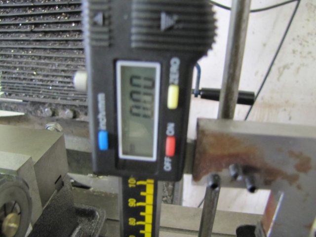
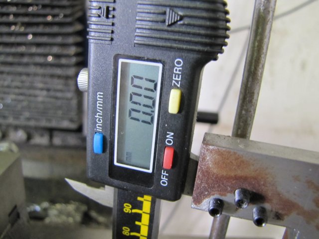
With the gauge reversed so I could see the display, It was zeroed. Analogue gauges won't have this option. :
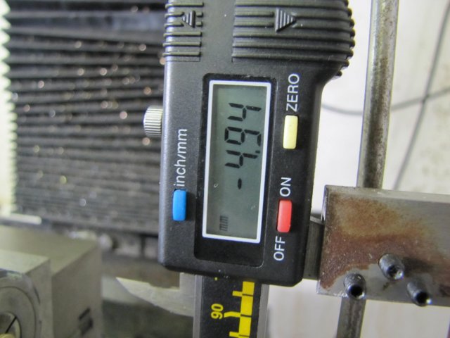
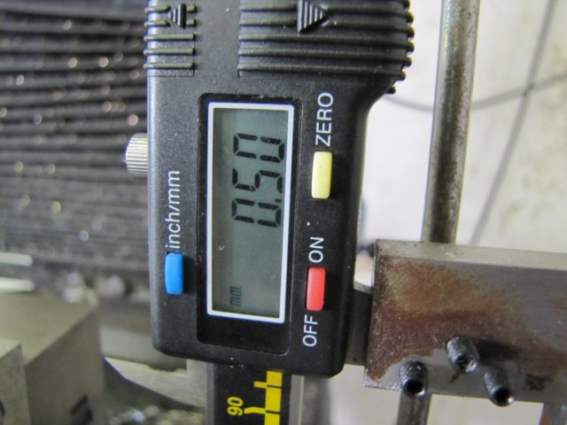
Having measured the workpiece diameter (9.88mm) earlier, it is easy to set the caliper to half of that (-4.94mm) to find the center line:
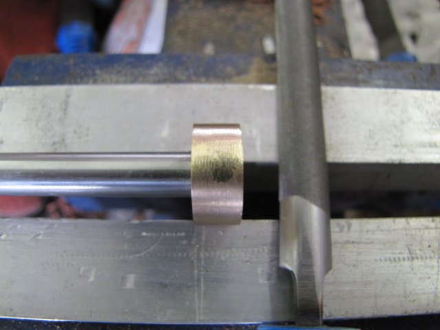
For reference, this is how the gauge compares to the workpiece after the last step:
With the digital gauges, it's easy to zero it off on the workpiece center :
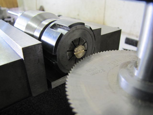
For the slot in the workpiece, I wanted a 1mm slot. To set the slitting saw on center for that, I needed to halve the width of the saw. 1/2 = 0.5. So I adjusted that offset on the caliper:
I used that to set the height of the slitting saw by
manually turning the mill spindle till the slitting saw blade _just_ touched the height gauge foot.
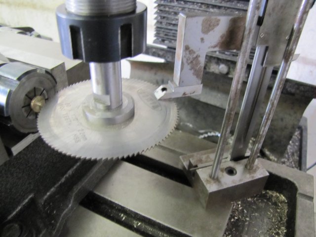
All slit and done - and the end of the mini how-to:
The final part:
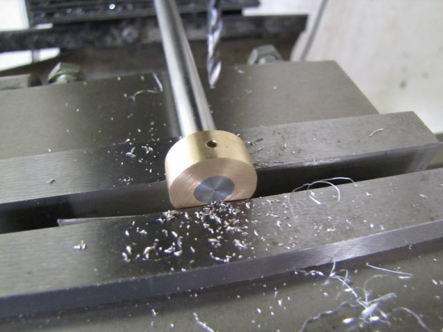
The crankshaft and web needed pinning. I poked a 2mm hole inn the lot - keeping the spindle speed on the low side so I wouldn't work-harden the stainless steel shaft while drilling:
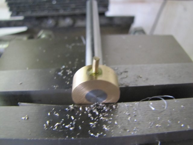
Don't adjust your monitor folks; a bad photo showing the 2mm bronze pin I knocked into the hole - with some retainer fluid included:
I snipped off most of the excess of the pin, and used a small hammer to peen it over:
Off to some filing, and the pin is just about starting to disappear:
All together after some emery work after the filing, and the pin is pretty much invisible. Have a mouse clicky on the photo and see if you can find it

:
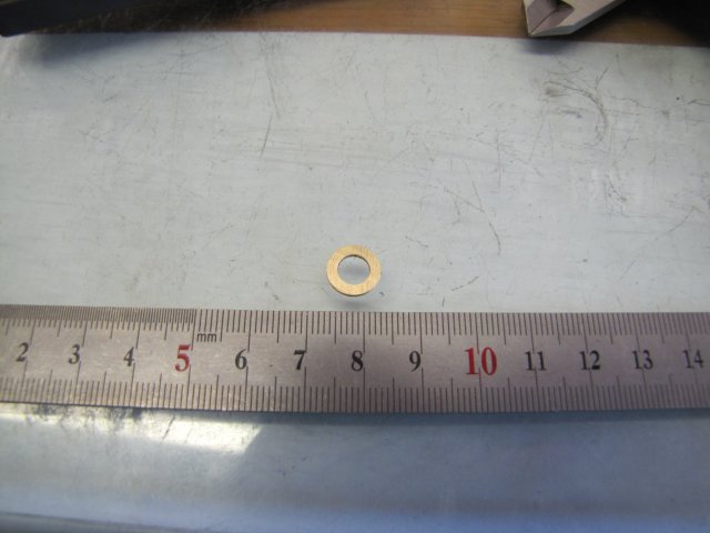
A part that's not in the plans: I turned up a thin washer to go between the cross-head and the web:
A trial fit,,,,,and there was some interference. The crank rod was still a bit thick on the fork end, and left a score in the cross head bore:
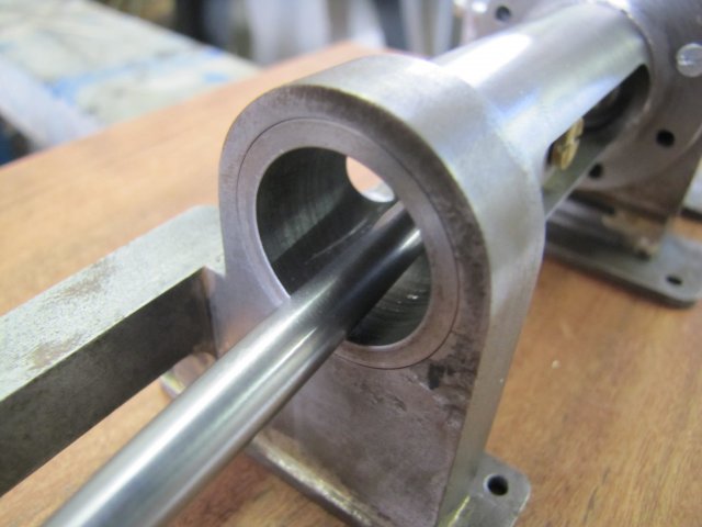
Some filing on the crank rod solved that:
Finally some family photos:
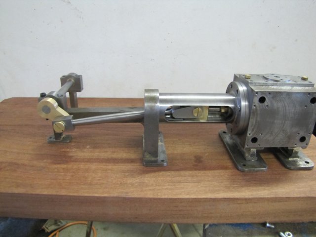
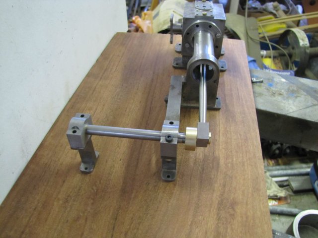
With the edges knocked off the crank rod, everything works well. A spacer might be needed between the crank web and the bearing though.
Kind regards, Arnold


