Author Topic: Arnold's take on the MEM Corliss  (Read 169538 times)

Offline zeeprogrammer

  • Full Member
  • *****
  • Posts: 6811
  • West Chester, PA, USA
Re: Arnold's take on the MEM Corliss
« Reply #120 on: March 17, 2013, 10:05:21 PM »
Nice work on the 'sticky-out-bit' Arnold.  ;D
Carl (aka Zee) Will sometimes respond to 'hey' but never 'hey you'.
"To work. To work."
Zee-Another Thread Trasher.

Offline Maryak

  • Rest In Peace
  • Full Member
  • *
  • Posts: 1818
  • Aldinga Beach South Australia
Re: Arnold's take on the MEM Corliss
« Reply #121 on: March 17, 2013, 11:14:38 PM »
Arnold,

Very nice  :NotWorthy: I hope your studies are progressing with the same level of success.

Best Regards
Bob
Если вы у Тетушки были яйца, она была бы Дядюшкой

Offline arnoldb

  • Administrator
  • Full Member
  • *****
  • Posts: 1341
  • Windhoek, Namibia
Re: Arnold's take on the MEM Corliss
« Reply #122 on: March 21, 2013, 04:30:25 PM »
Thanks for checking in everyone  :praise2:

Jim, those are nice tips on gluing Teak - I didn't know that - Thank you!  I'll see how things pan out with the "loose" joint - it does mean that there will be separate stresses on the cylinder and the flywheel mountings, and the base and mounting bolts have to take these...  If there are problems, I'll Loctite or solder the loose joint.

Bob, the studies are going well thanks.  I'm waiting for my new PC to be delivered, so most of it is at a standstill right now.

Fortunately, with the studies at a standstill and a public holiday here in Namibia today, I got a bit of shop time  ;D

First the one block of steel from the last post was milled to size, then, after a bit of marking out and a whack with a punch for the center of the hole, was clocked up in the 4-jaw and drilled out to 19mm:


Next, bored out to a close 27mm to match the cross-head guide:


Off to the mill, and I milled out the step needed:


To round it over, I used the cross-head guide as support and milled off the excess in facets:


Milling complete:


I put in a bit of effort with a couple of files, and soon the facets were gone and the bit is nicely rounded over:


After that I milled, drilled and filed the bits of 3mm plate to size and shape and rounded all the necessary corners.
The long block of steel with the sticky-out-bit still needed some holes drilled into it as well.
I set of, and immediately made a stuff-up  :facepalm2: - even though I used the edge finder to locate all the needed dimensions, I forgot to center back up on Y after I found the right hand edge and dialed in the offset for the hole:


Rather than re-making the workpiece, I used a 3mm end mill to open up the hole at the correct location.  This won't be visible, so for now I'll call it "character":


A 2.5mm hole was drilled 18mm further in from the edge - this time on the center line.  This will later be tapped M3.  As a last step, I drilled a 6mm hole right on the bottom edge of the workpiece.  This is to receive a bit of 6mm rod that will be drilled and tapped to mount the lever that links the valve rods:


A photo of the bits as I stopped today.  The closest vertical edge in the photo next to the valve lever hole still needs a bit of rounding over, and I have to make the bit where the valve lever will be mounted - then I can solder the lot together:


Much to my surprise, everything fits really well together when assembled on a flat surface - with none of the mountings too high or too low - I'm really happy with that  :):


Kind regards, Arnold
Building an engine takes Patience, Planning, Preparation and Machining.
Procrastination is nearly the same, but it precludes machining.
Thus, an engine will only be built once the procrastination stops and the machining begins!

Offline vcutajar

  • Full Member
  • *****
  • Posts: 2555
  • Marsascala, MALTA
Re: Arnold's take on the MEM Corliss
« Reply #123 on: March 21, 2013, 04:35:43 PM »
Nicely done Arnold.

Vince

Offline Jo

  • Administrator
  • Full Member
  • *****
  • Posts: 15305
  • Hampshire, england.
Re: Arnold's take on the MEM Corliss
« Reply #124 on: March 21, 2013, 05:34:52 PM »
You are making some really good progress there Arnold.  :ThumbsUp:

Jo
Enjoyment is more important than achievement.

Offline metalmudler

  • Full Member
  • ****
  • Posts: 57
Re: Arnold's take on the MEM Corliss
« Reply #125 on: March 21, 2013, 06:17:20 PM »
Hi Arnold,
You definately dont know me. I would like to thank you for taking the time to upload your pics,this is something i lack the time for.Im Shit with words,but pictures tell 1000 words.I hope to be uploading some of my stuff soon. Your stuff is good m8 ;)
It's not done, until it's DONE... Even then there is something else to do to it !..

Offline Don1966

  • Full Member
  • *****
  • Posts: 6818
  • Columbia, MS
Re: Arnold's take on the MEM Corliss
« Reply #126 on: March 21, 2013, 11:53:29 PM »
Hi Arnold, it's looking good and I do Like the way you used the guide truck to mill the mounting flange.  :ThumbsUp: Great work as usual.

Don
« Last Edit: March 22, 2013, 01:14:38 AM by Don1966 »

Offline zeeprogrammer

  • Full Member
  • *****
  • Posts: 6811
  • West Chester, PA, USA
Re: Arnold's take on the MEM Corliss
« Reply #127 on: March 22, 2013, 12:52:40 AM »
Very nice file work Arnold.
And always an interesting post.
Carl (aka Zee) Will sometimes respond to 'hey' but never 'hey you'.
"To work. To work."
Zee-Another Thread Trasher.

Offline Captain Jerry

  • Full Member
  • ****
  • Posts: 1074
  • Summerfield, FL USA
Re: Arnold's take on the MEM Corliss
« Reply #128 on: March 22, 2013, 01:07:00 AM »
Nice work, Arnold.  Looks like a very solid fabrication.

Jerry
NOTARY SOJAK

There are things that you can do and some things you can't do. Don't worry about it. try it anyway.

Offline arnoldb

  • Administrator
  • Full Member
  • *****
  • Posts: 1341
  • Windhoek, Namibia
Re: Arnold's take on the MEM Corliss
« Reply #129 on: March 23, 2013, 07:04:03 PM »
Thanks all for checking in  :praise2:

Paul, yes, I don't know you, but I did read your Intro (I read each and every single post here on MEM).  I've not been as diligent as I should be about welcoming our new members  :-[ .
Pictures may be worth a thousand words, but a couple of words can make a picture worth even more.  Don't be afraid to use words - it works much like learning to use tools; the more you use them the more comfortable you get about using them.  Looking forward to your posts mate  :ThumbsUp:

Well, my new PC is still a no-show, so I guess I've got most of the weekend for machining  :)

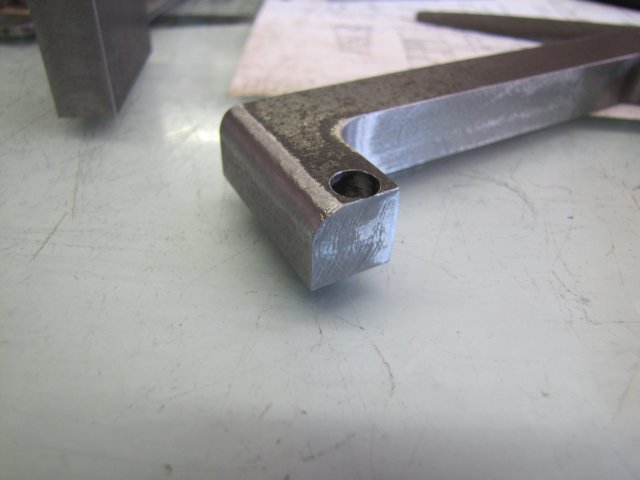
First up some file-work; I just rounded over the end of the long bit by eye.  It's not critical, and just for looks, so if it looks good enough it is good enough:


Then I started to solder the bits together.  First the cross-head guide carrier to the long section - making sure that they were nice and square (no photo) then the foot at the end of the long section:


When I silver soldered the cylinder mountings, I used the Sievert propane torch, but found that even though it gave a lot of heat fairly quickly, it didn't work as nice on the steel as it does on copper and bronze.  So I used the oxy-propane kit; this makes a much hotter, but smaller flame, but with the steel not conducting away localised heat as quickly as copper, it was easy to get the joint areas heated up very quickly to soldering temperature - and a dab with the solder stick on the opposite side of the joint after the flux ran and the metal on that side was dull red made the solder wick right into the joint toward the flame side.  I found this much more controllable - though I still did make a bit of a mess in some spots  :Lol:

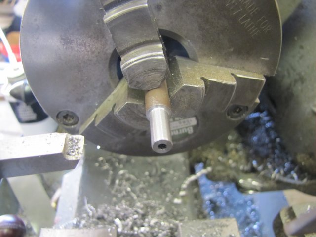
I nearly forgot about the valve lever mounting - fortunately I had not soldered the "larger" base plate on yet.  I turned up the mounting from some steel, and drilled it to tap M3.  The plans says M2.5, but I still don't have M2.5 taps, and the one set I've been able to find costs N$400 - that's a bit dear right now...  M2 seems a bit light-weight for this link, and there is enough room to use M3.  I didn't tap the hole yet; M3 threads are quite delicate, and between oxidisation from the heat while silver soldering and pickling afterward, they might just be eaten away:


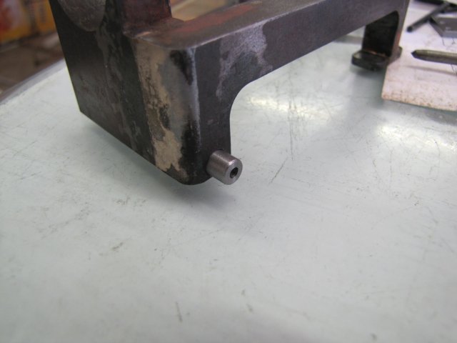
The pivot pin installed in the workpiece - I removed the oxides from the previous silver soldering session in the hole by first twirling a 6mm drill bit in the hole, and then rubbing off the rest with a bit of rolled-up scotch-brite:


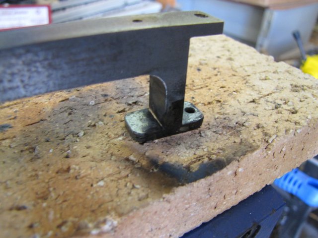
Next I cleaned up the bottom of the workpiece with scotch-brite as well to get rid of the crud there, dropped some flux and a 1mm long bit of snipped-off silver solder in the pivot mounting hole before inserting the pivot mounting, and lastly added some flux between the upper bit and the mounting plate.  I set the lot up on the flattest bit of fire-brick I have, and gave it the welly with the torch, once again heating from one side and feeding the stick from the other side once the flux flowed and the bits of metal around the joint was dull-red.  After cooling a bit, it looked like this:


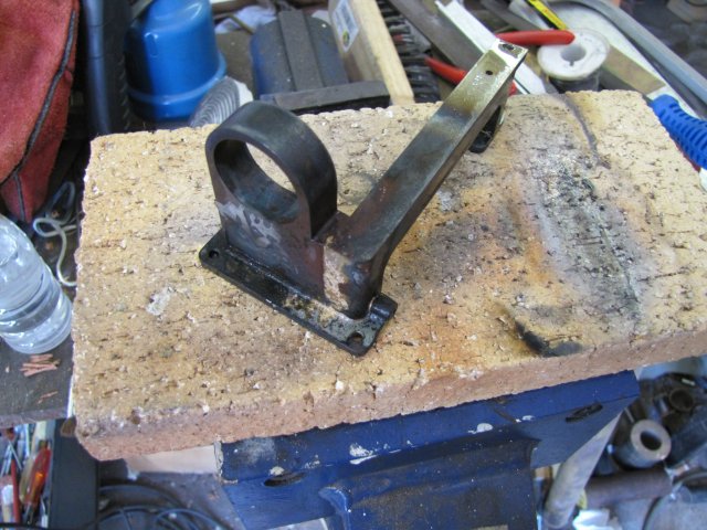
I'm slowly growing more confident with silver soldering - things still are not as nice-looking as other members show, but each time I learn something new.  How to maneuver the torch.  Where to apply the heat.  When to start applying solder.  How much flux to use.  How much solder to use.  I'm still getting a lot of that wrong, but it is improving.  I still tend to apply too much flux and solder - though I think for today's session, I got the flux proportions better.  Still too much solder though.  And to put that in perspective, I used only about 10mm of 1.6mm solder rod in total today...  More practice needed  ;) .  Another scary bit about silver soldering is the way the workpiece looks once done.  It's always that "Darn - how will that lot EVER clean up" feeling.  I still get that feeling, and the photo above shows why...

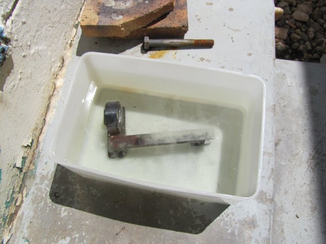
Off to the kitchen, and I purloined a suitable plastic container from the kitchen cupboards.  While I was there, I filled the kettle and put it on to boil.  The kettle takes about 1.75l of water, but I stole enough to make a cup of coffee before pouring the rest in the plastic container and adding about a table-spoon full of citric acid to that.  Taking the coffee and the acid tub to the shop, I plonked the workpiece in the hot citric acid (outside on the shop step) , and it immediately started to fizz up in there:


Once the coffee was finished, I took the workpiece out, gave all the still-black bits a scrub with a small stainless-steel wire brush, and plonked it back in the pickle.  That was right about lunch-time, and as I was feeling a bit peckish, I went indoors and had a nice ham and cheese sandwich in front of the telly with the AC on to cool down.  Happened to watch a guy called "Guy" eating grits and sausage sauce on the Food channel  :-X :paranoia:

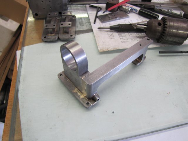
Back to the shop, and I rinsed the workpiece very thoroughly with clean water.  A good scrub-down with more scotch-brite, and it looks OK - except for where I applied too much solder:


On to some work on the base.  When I planed down the sides of the planks that I glued together for the base, I didn't get them entirely square, so the glued base ended up with a slight rise in the middle.  The last time I tried to plane a flat sheet of wood down was back in my junior high school days - about 1996...  And that was in a well-fitted woodworking shop...  Well, I have what I have, so I soldiered on - clamping the plank in different orientations and just manually planing it down:


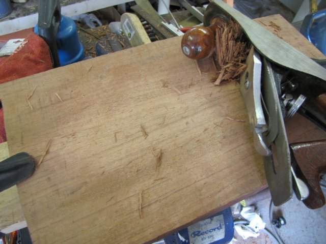
Once it looked about flat enough, I took the orbital sander to it - outside again.  Things turned out surprisingly well  :) :

 :o 
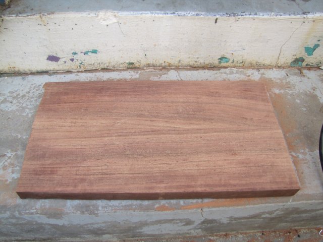
There's quite a large difference in the wood colour between inside the shop under fluorescent lighting and outside in natural light when photographed!

All the sides were still pretty rough, and there was no convenient or safe way to run those past the circular saw in it's stand, so I took it out of the stand, set up some trestles outside (under the car-port - so nice and shaded) and started trimming away:


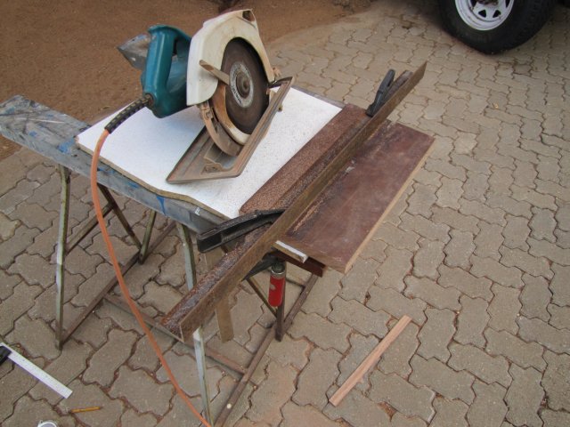
The underside of the plank is still very rough, and I'll need to make a plan with that.  The circular saw blade is no longer in prime condition, and I have no way to sharpen it yet, so it hacked some corners off the wood, but that I'll fix with a router and an edge-shaping bit later on.

A family shot with all the bits in their approximate locations:

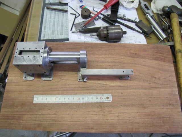
 :) And Yes! - they all sit flat and fit together  :whoohoo: - even on the wood!

There's lots of flaws for everyone to see in the overall picture, but somehow I don't mind that.  This project has been a lot of hard work so far, and for the most part have taxed my own machining abilities to the limit with working in steel rather than non-ferrous metals, making built-up assemblies and even the wood-working.  I'mHavingAHellOfALotOfFun  ;D

Kind regards, Arnold
Building an engine takes Patience, Planning, Preparation and Machining.
Procrastination is nearly the same, but it precludes machining.
Thus, an engine will only be built once the procrastination stops and the machining begins!

Offline Jo

  • Administrator
  • Full Member
  • *****
  • Posts: 15305
  • Hampshire, england.
Re: Arnold's take on the MEM Corliss
« Reply #130 on: March 23, 2013, 07:20:35 PM »
Arnold,

One of the reasons you were having problems silver soldering is that the piece you were working on is out in the open, so it has lots of opportunity to radiate its heat away. Try adding a couple of bricks close behind the work or even a couple of bits of scrap metal. Ok they will warm up but they will radiate the heat back towards the work  :ThumbsUp:.

And you might want to invest in some of the really thin silver solder, its really good for making little rings out of and putting around the joints you are trying to make.  ;).

Jo
Enjoyment is more important than achievement.

Offline Alan Haisley

  • Full Member
  • ****
  • Posts: 693
  • Fuquay-Varina, North Carolina, USA
Re: Arnold's take on the MEM Corliss
« Reply #131 on: March 23, 2013, 08:30:16 PM »
There's lots of flaws for everyone to see in the overall picture, but somehow I don't mind that.  This project has been a lot of hard work so far, and for the most part have taxed my own machining abilities to the limit with working in steel rather than non-ferrous metals, making built-up assemblies and even the wood-working.  I'mHavingAHellOfALotOfFun  ;D
Me too! It's great watching the problem solving.  :cartwheel:
Alan

Offline vcutajar

  • Full Member
  • *****
  • Posts: 2555
  • Marsascala, MALTA
Re: Arnold's take on the MEM Corliss
« Reply #132 on: March 23, 2013, 11:16:19 PM »
Quote
There's lots of flaws for everyone to see in the overall picture, but somehow I don't mind that.

Arnold, I can't see any and if there are any they are well hidden. :cheers:

I suppose fabricating the guide and crankshaft support is the best way to go.  I cannot imagine myself hogging it out from solid.

Vince

Offline Don1966

  • Full Member
  • *****
  • Posts: 6818
  • Columbia, MS
Re: Arnold's take on the MEM Corliss
« Reply #133 on: March 23, 2013, 11:49:41 PM »
Looking good to me also Arnold, I see no flaws. Always a pleasure to see more progress.

Don

Offline swilliams

  • Full Member
  • ****
  • Posts: 896
  • Canberra Australia
Re: Arnold's take on the MEM Corliss
« Reply #134 on: March 24, 2013, 11:16:59 AM »
Looking great Arnold, Shaping up to be a really great engine  :D

Steve


SimplePortal 2.3.5 © 2008-2012, SimplePortal