Thanks All

Jo, like Tel said, I didn't want that ring slapping around. You shouldn't have mentioned that good tap of yours - it jinxes it

. The #2 2mm tap I broke has a whole story behind it... The only tap I ever broke before this one was also a #2 2mm - in some work-hardened stainless. The first cut this one made was right trough that same stuff to finish that hole, so it may have been slightly doomed right from the offset

.
Good luck Vince

- or rather, Happy Machining! Yes, I'm following along, and all of us that's busy building it can compare notes
. Once I get around to the flywheel, things may just involve a lot of heat and a big hammer to start off with... I'm struggling to find material for it locally, and my budget's a bit tight at the moment, so I'll have to improvise a bit...
Bill, you're doing a great job on the Wright Brothers 1903 - finish that one off first
. The Corliss is still untested, so it might be good to check things out before you start on it.
Don, not a new camera - the same one, still with the broken corner

The only difference is I have to take the photos from a bit further away compared to my previous builds, as the parts are so much bigger. The cylinder block on its own is bigger than a couple of engines I've built

Dave, thanks bud, but nothing like that here on the savannah. I have a sheet of perspex that I got especially for making up a chip-screen - but that's just another round tuit... The only times I remember I need to make it is when a job like this comes along on the lathe, or when I forget to check which way the chips will go when fly-cutting with a carbide tool on the mill

Progress is a bit slow on the build, but I've had a couple of challenging "work" work assignments thrown my way. Last Sunday, I took the day off engine building for some good old-fashioned book studying. I planned a full day in the shop today, but while running some errands this morning, I got a call from a friend who needed some help. Family and friends take precedence, so I only ended up with half the shop session I had planned.
I started off with centering the rotary table on the mill, moved the 4-jaw chuck to the rotary table on the mill, and drilled the mounting holes in the flange:
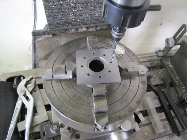
You might notice the piece of wire holding the "parallel" (packing as Tel called it) is gone here. I needed to tap the packing around a bit to prevent the drill catching on it when breaking through the holes. HSS drills don't like drilling into hardened bearing shells.
Back to the lathe, and I used a grooving tool to trepan a ring into the workpiece at about 1mm larger in diameter than needed. I wasn't feeling in the mood to grind up a new toolbit for this job, and this grooving tool had
just enough clearance on the "outside" side at this diameter, though it wouldn't do the job completely. It also does not have a very deep sharpened reach, so when I saw it starting to raise a burr on the inside ring, I stopped:
With the bandsaw in vertical mode, I cut away most of the outside. The groove made things easier to follow and get fairly close. While the bandsaw blade can follow a slight curve, this ring is much too small for it to follow, so I cut away things in sections; corners first at about 45
o to just intersect with the groove, then the smaller left-over bits either side and so on:
I didn't want to leave too much "meat" on the ring, as the next step was soft-soldering it to the "pipe" section. The tin/lead solder I used is not very strong, and while more than adequate for this specific application in it's final use, it would likely not stand up to machining too much of an interrupted cut to get things to size.
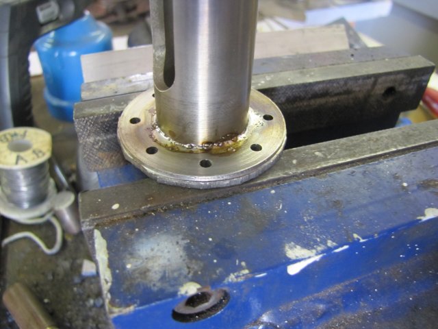
Next up, the soldering. After cleaning oil residues of the two pieces with some methylated spirits, I just coated the inside of the ring with some plumbers' flux, stuck the bits together, checked alignment of the slots in the pipe section to the holes, and added a ring of solder:
Can anybody spot the boo-boo about to happen here ?

A bit of heat from the plumber's torch from below had the solder flowing and the joint made - definitely not as pretty as I'd hoped, but it would do:
Spotted the boo-boo yet? No? The "pipe" section was upside-down. The grooves in the "pipe" section is offset closer to one end, and I'd gone and soldered it in the wrong-way around

. So I re-heated everything took it apart, wiped away as much of the solder as possible with a bit of kitchen paper, and re-soldered it the correct way around. Yippee... Job done! Uhrm... Oops... No... Rats

I didn't check the alignment of the grooves in the pipe section relative to the mounting holes in the flange

Stupid bugger

. So once again a bit more heat till the solder flowed, and I rotated the pipe section with a leather glove to match up correctly with the mounting holes ,purely by eyeball MK1. This is not overly critical - the cross-head has a lot of contact area in the pipe section of the cross-head guide, so if it looks OK it should be OK. The critical bit here is that the pipe section be very square to the flange, and the inside lip I machined on the flange earlier helped with this.
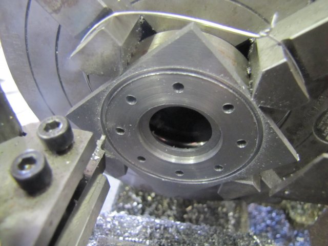
So, after all the soldering boo-hah, I finally got the workpiece back on the lathe to turn the flange to the correct diameter. I clocked it up in the 4-jaw chuck again:
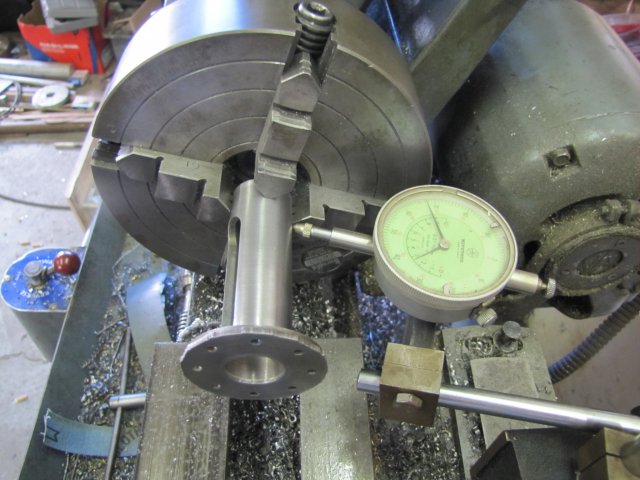
There was no real need for this; I could just have used the self-centering 3-jaw, but I like a bit of a personal challenge. And anyway, my 3-jaw chuck is out by miles and a bit bell-mouthed, and I'd rather take a bit of accuracy here. With the cut-outs on the pipe section, the 3-jaw would also be more inclined to distort the workpiece.
One bit of kit I got with my lathe is very nice indeed - though I haven't mentioned it very much. The revolving tailstock center has interchangeable bits, and besides the normal sharp 60
o center, it has a larger cone center and so on. I fit the cone center for the next step; it's larger than the bore in the pipe and added some rigidity:
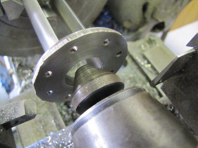
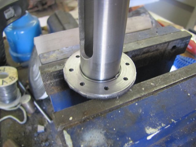
And turned the flange down to size. Light cuts, so as not to break the soft soldered joint:
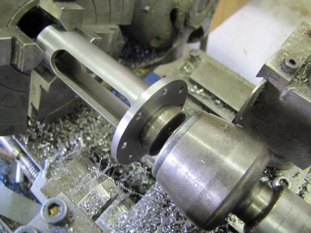
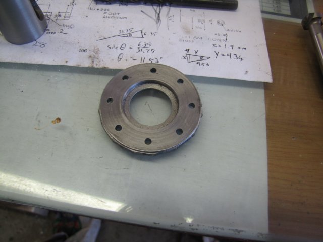
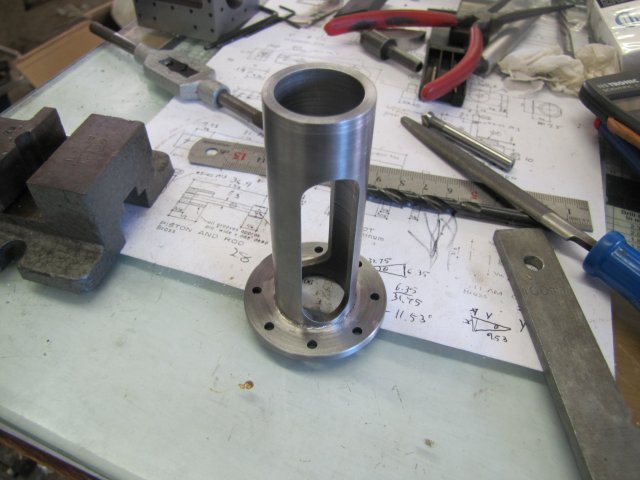
Finally, I had the cross-head guide done:
This engine is taxing my available material, so I settled on some 25x5mm flat bar to start the steam and exhaust cover plates from:
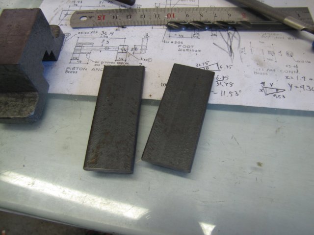
Those bits were machined down to length and width (60x23mm), and then I spotted the hole positions for drilling, leaving a lightly spotted hole in the center for more machining later on:
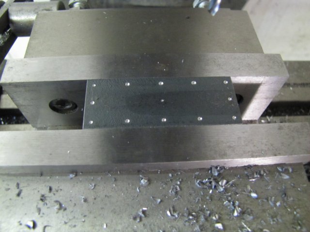

I really need to get myself a set of parallels; that lot was just mounted by fingertip-feeling across the top of the vise's fixed jaw. It's not good practice and a nonchalant personal vice I need to address...
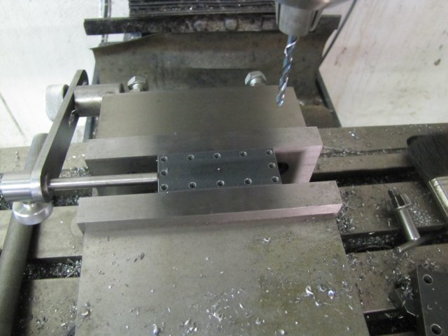
After a bit of drilling, it looked like this:
The second one followed, and I two covers-in-making. A bit thick, but in progress. The result of today's work:
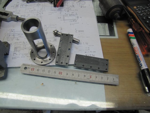
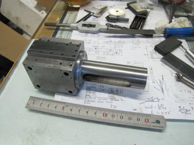
Not a true assembly shot, but this is what things looks together like right about now:
Kind regards, Arnold


