First off, many thanks to the MEM team for designing up this engine

. It was (and still is!) fun to see the design come together - but my own role is insignificant, and like Jo mentioned in the plans section, just involved some heckling from the side lines. She's much too modest about her own and Dave's contributions though

.
The least I can do is to build the engine. As those that know my habits by now could guess, this build will be in metric. I'll leave the imperial one to Tel

.
Bob kindly sent me the CAD files. My initial thoughts were to keep to the original exact dimensions and just convert things to metric as needed. However, a lot of the crucial dimensions for the operating geometry and hole sizes are difficult to just convert straight-off, so I scaled the plans to metric using a factor of 24 instead of 25.4. This will leave the engine a little smaller, but the conversion means that nearly all values scale to easy-to-use metric sizes.
This is by far the biggest engine I've attempted, and there will be some new learning curves involved in terms of work holding, set-ups, and tooling use. The flywheel is pretty much at the limits of what my lathe can do, and I'm not sure how I'm going to go about making/machining it yet. I do have some ideas about that though.
First off, a start on the engine block. Last weekend, the band saw was put to work to cut a lump off some 60x60mm hot-rolled steel bar I have:
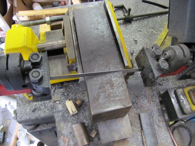
After letting the saw go about half-way through, I stopped it, and rotated the stock to let the saw finish on a smaller cross-section. The blade I have in there is a bit fine for this thickness of cut.
The stock for the cylinder block with a 150mm (6") rule to give an idea of size.


- I just noticed it's sitting on the plan sheet for Elmer's #25. Massive difference in size!
On to the mill, and a bit of fly-cutting to square up the block of steel and bring it down to size. None of the edges were square or true - I followed a method Bogs once posted to get things right. (John: if you find some time, could you perhaps re-post your method please ?) :
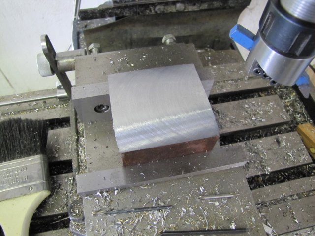
I use a carbide-tipped left hand turning tool that's been re-ground slightly to give adequate clearances for this in the fly-cutter. At 1200rpm and a 0.5mm per pass depth of cut, my mill makes short work of things with a good cranking speed. Just kicks up a heck of a noise, and the surface finish isn't as good as with a nicely honed HSS bit and lower speed. And those chips come flying of blue-hot, so there's a bit of "dancing" involved to duck them...
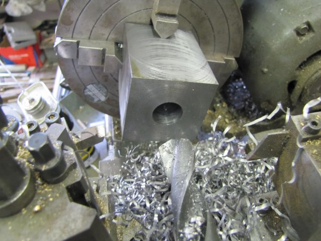
Once the block was down to size on the top,bottom, front and back sides (51x51mm), I had to make a choice. Machine the cylinder faces and cylinder bore on the mill, or use the lathe. Either method would work, but the largest drill I have is 19mm, and the cylinder needs to be bored out to 27mm. On the mill, this would mean I'd have to use the boring head to open up the cylinder to size. I don't mind using the boring head, but it can be a pain and slow to adjust a lot of incremental cuts on it. I'd have the luxury of using the DRO to drill the cylinder cover mounting holes afterwards though. On the other hand, it's quicker for me to bore this on the lathe... And face the crankshaft end of the cylinder really true... And the rotary table is in place on the mill to drill the bolt holes... So off to the lathe, and clock up the block in the 4-jaw and drill some holes - I started with a center drill, followed by a 7.5mm drill through (It's nice and stiff, and as it's not used a lot, nice and sharp as well), then 13mm, 16mm and finally 19mm:
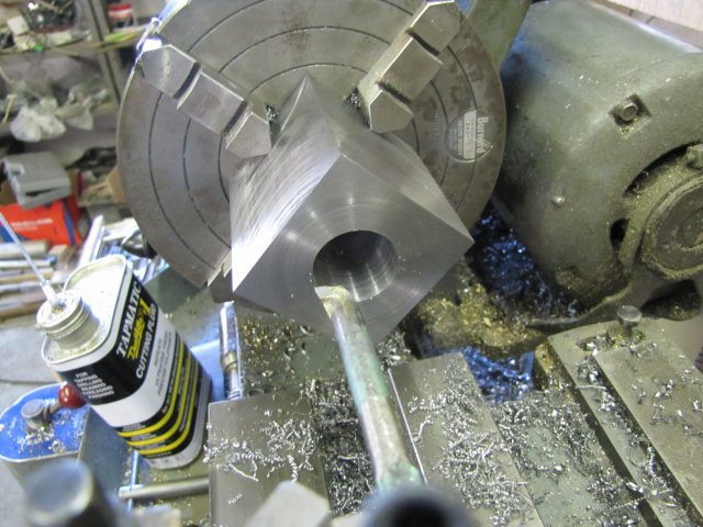
Next to bore out the cylinder to size, and here I hit a snag... My biggest boring bar for the lathe is actually much too thin for this job
. The machining weather service immediately predicted severe spots of chattering for the rest of the day. So... Use the thin boring bar, or make up a new thicker one

... My materials stock is a bit low, so I went with the thin carbide-tipped boring bar. I gave it a good honing on a diamond stone to get a keen edge on the cutting surface, and started boring out the cylinder - with a 0.5mm feed at a time - making the hole bigger by 1 mm on each pass. It works OK and not much chattering. My shop session got interrupted before I could finish the bore; a ring from the cell-phone announced a friend at the front gate, so I snapped a last photo:
Hopefully I'll get to finish the bore and drill a lot of holes tomorrow.
Kind regards, Arnold


