Thanks Jo; I'll give that a try as well

. One thing I keep forgetting is to try and make up my own "silver solder paste" by filing a bit of solder down over a bit of paper to catch the filings, and then mixing it with flux. Have to experiment with that one as well at some stage...
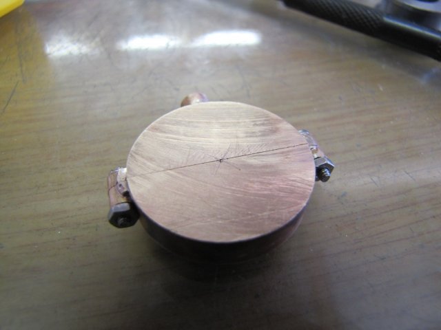
Yesterday was a lost cause; I had to pay attention to other matters, but today I got some more bits done. First of was more work on the eccentric strap; first, I marked the center:
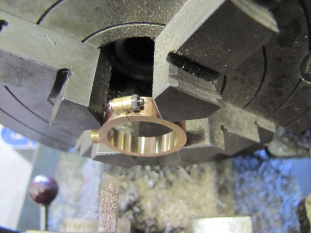
Then clocked it up in the 4-jaw, taking care not to be too heavy-handed while chucking it up:


I REALLY need to make a pump-center...
I very carefully drilled it out to 10mm - keeping the feed rate low to prevent the drill "grabbing" in the bronze , and from there used a small sharp boring bar to bore it to final size. The eccentric ended at 22.05mm, so I bored this to 22.1mm to give a bit of room to form the bearing surface:
Not exactly a thing of beauty after clean-up, but it will do for now. I'll make smaller nuts; the standard M2 nuts are too big:
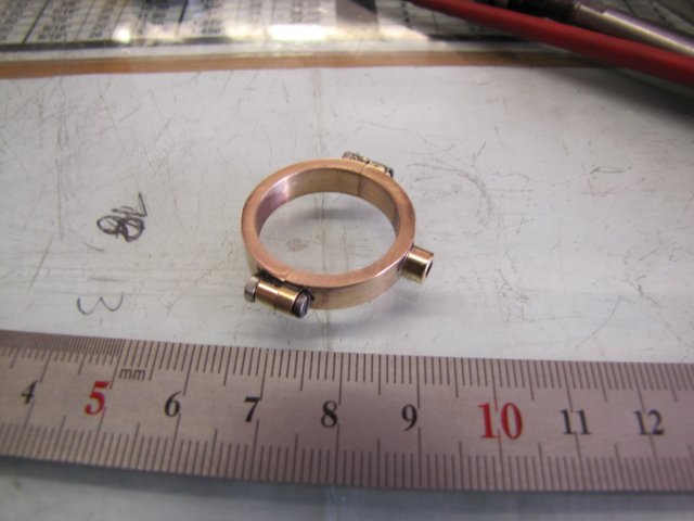
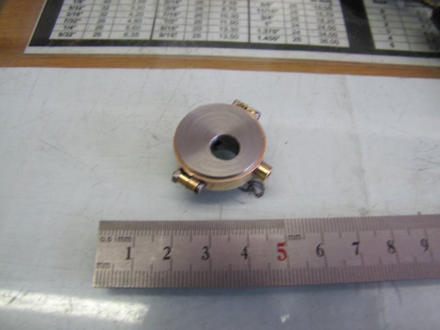
It turned out to be a very nice fit on the eccentric; turning smoothly, but without discernible play:
Next, a bit of 2mm brass plate for the lever arm. The plans call for 1.5mm, but I had a choice of 1.2 or 2mm, and the 1.2 could be a bit flimsy, so I went with the 2mm. Holding smaller bits of plate like this for drilling can be problematic, but it's a breeze on the tooling plate I made:
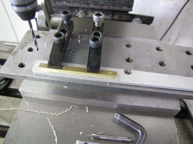
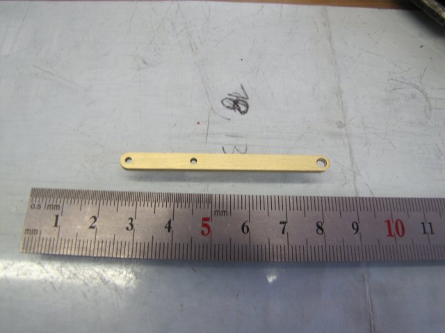
Some rounding-over and a bit of clean-up, and the lever was done. the bigger 3mm hole on the one end is not exactly to plans; I made the thread in the base for the pivot M3, hence the larger hole:
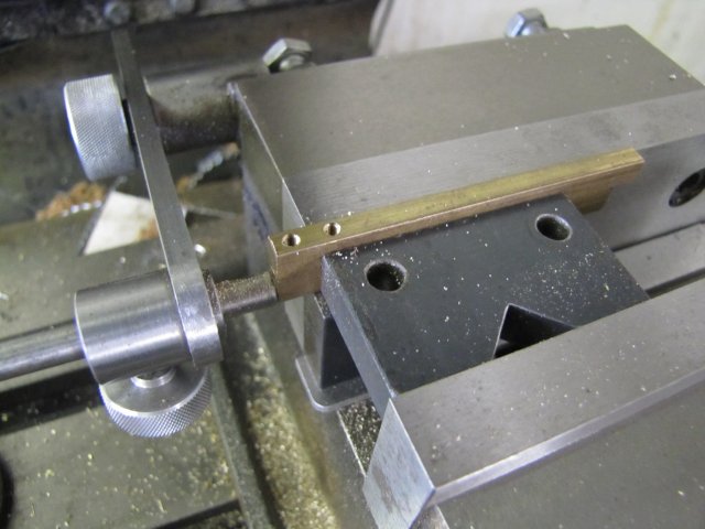
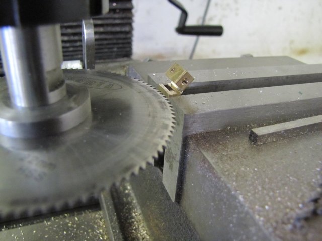
Like Vince mentioned, the forks for the two eccentric rods are identical, so I also made them as a pair from some 12.7x4.7mm (1/2" x 3/16") brass flat bar I have. I used the edge finder to find the middle of the bar on the Y-axis, and the end on the X axis. I started to mill the center out wit a 2mm slot drill, but after I reached about 5mm deep, it snapped... On the 6mm deep level, another one snapped, even though I was very careful with the feed-rate. Not wanting to break my entire supply of 2mm mills on these pieces, I decided on another tact. I set up the vise stop so I could flip the workpiece upside-down, and drilled and tapped the M3 holes for the rods - leaving 1mm additional gap between them for a 1mm slitting saw to slit the two bits apart:
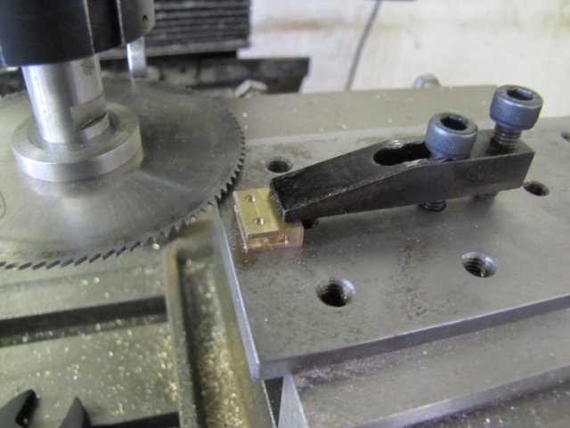
Then I slit off the two still-joined pieces from the parent stock at the needed length, and once again reverted to the tooling plate; clamping down securely on the end of the workpiece in the area that would not get material removed. I didn't want to have the workpiece come loose once I started removing material. I finished the slots with a 1mm slitting saw (that's the thickest I own) - one cut top and one cut bottom:
Then I slit the pieces apart - leaving the tiniest little burr keeping them together. It saves having to play hide-and-seek on the shop floor to find the workpiece as it gets flung away if fully slit off... :
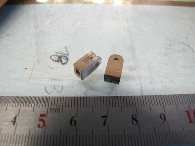
Some more rounding over and clean-up, and I had the two forks. I just noticed there's still quite a big scratch left on the right-hand one
:
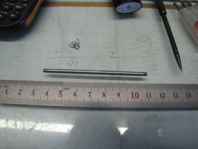
A bit of 3mm stainless steel volunteered to get threaded either end with a tailstock die holder, and I had one eccentric rod. I intentionally left it slightly long at this point:
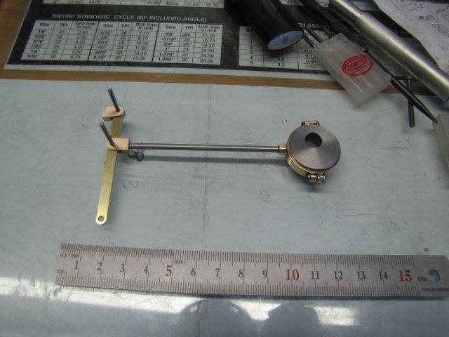
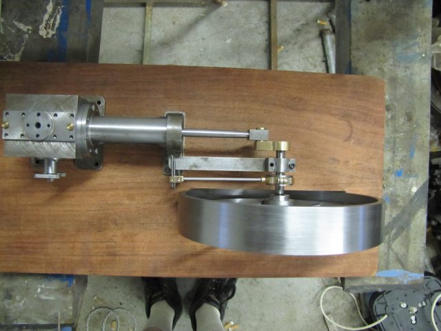
The results of today's work assembled together. Broken slot-mill shanks makes nice holding-together pins

:
I couldn't leave it at that, so I disassembled the engine a bit first. When I made the bits of the frame, I didn't tap the one bearing mounting hole, nor the thread for eccentric pivot, so I quickly, but carefully, did those. Then I loosely assembled things again, with the eccentric set roughly at 90
o to the crank, and checked how far the eccentric lever pivoted to either side from "straight-up" while turning the flywheel. As mentioned earlier, I left the eccentric rod a bit long. I had to shorten it by another 2mm and add four turns of thread to the eccentric rod, and things ended up pivoting evenly and equally both ways by eyeball MK1. That should just about do for adjustments on "this" side of the eccentric pivot.
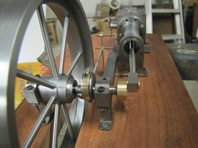
From a top assembly view, you can see that I need to move the eccentric slightly more toward the flywheel to get it in it's correct place:
The pivot rod is pretty much upright at the full piston travel to either side of the cylinder:
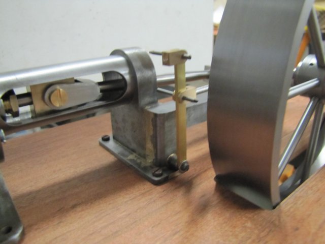
Still crude, but it's slowly starting to resemble an engine

:
One thing I would do differently
if when I have to do it again is for the screws/bolts on the eccentric strap. Rather than drill clearance through both parts to use a bolt or screw with a nut, I'd drill through the "flywheel side" for clearance, but tap the "engine side". It was a real bugger to get the bottom nut into place for installation; I eventually resorted to contorting my index finger with a dab of grease on it to hold the nut in place through the flywheel to get the nut into position. Once I make the smaller nuts, that will be a heck of a load of "fun"!
Kind regards, Arnold


