Hi Guys
I have needed to get an update posted on the Pacific but first want to say thanks to Art, Jim, Bill & Jared for your comments and taking the time to follow along with my project.
Next; I decided to work on a muffler for the engine; there are no plans for a muffler and I have never seen a picture of an original, either in the flesh, or on copies of original advertisements. Maybe Pacific never offered a muffler for their engines.
Not being one that enjoys listening to the bark of a straight pipe all day long at a show; I decided early on that my engine would have a muffler. I wanted to create something that looks like it belongs on the engine; so using modern pipe fittings wasnt going to work.
Hiding in this nice US made ¼ elbow; hopefully is the start of the base casting for my muffler.
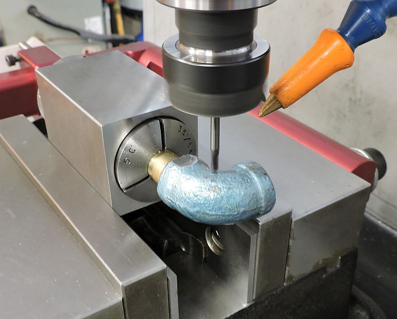
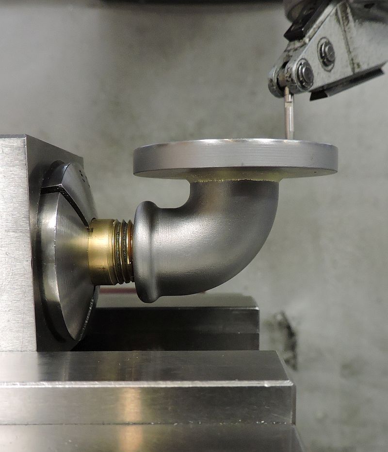
The elbow was Loctited to a brass nipple and indexed so that both sides could be surfaced. Each side was surfaced using a 3/32 carbide ball end mill.
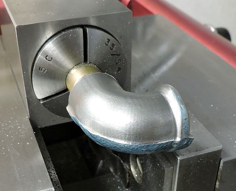
Here the first side has been completed; then it gets flipped over and the other side gets the same treatment.
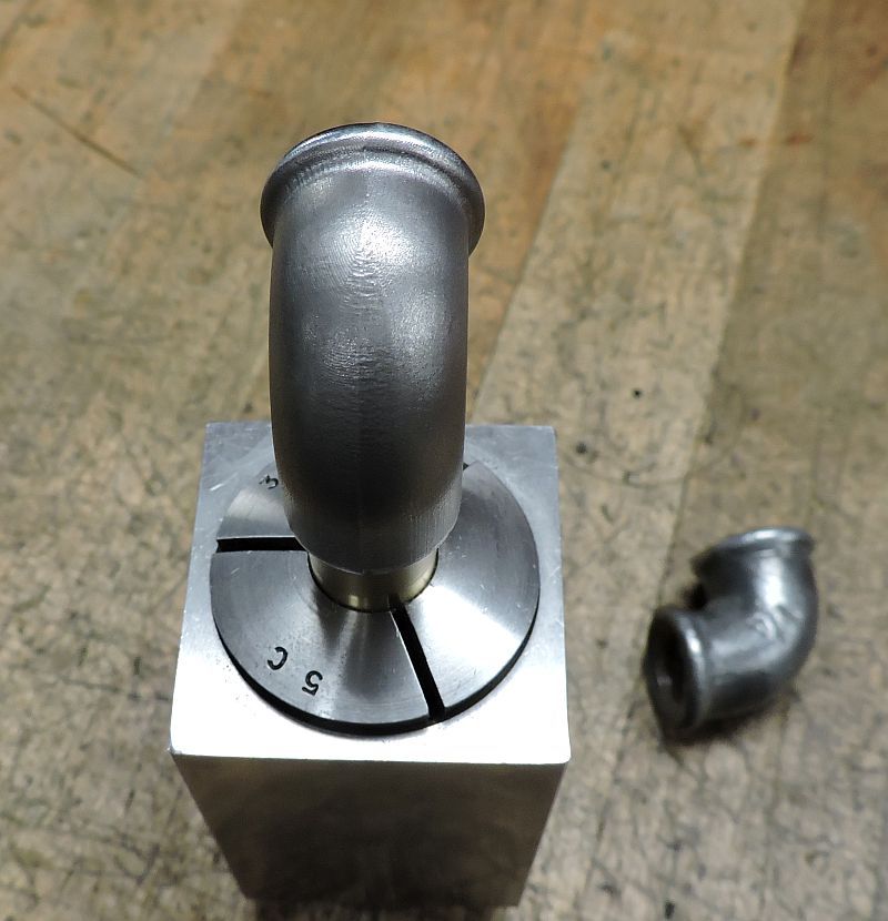
Here is the elbow after surfacing both sides. Fortunately there was enough material on the fitting to allow this to be done.
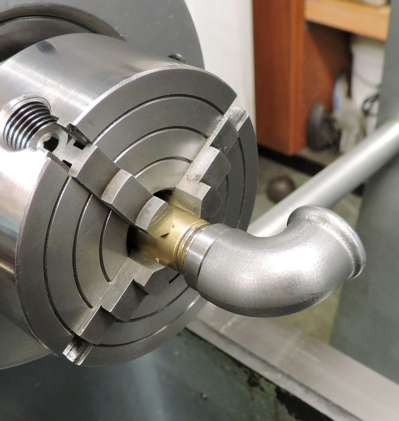
Before removing the nipple from the elbow it was put in the lathe, dialed in, and a register machined to accept the muffler mounting flange.
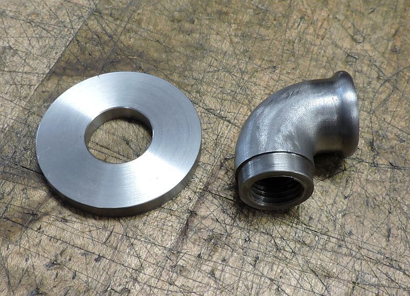
The elbow was heated to release the Loctite and removed from the nipple and shown here with the start of the flange.
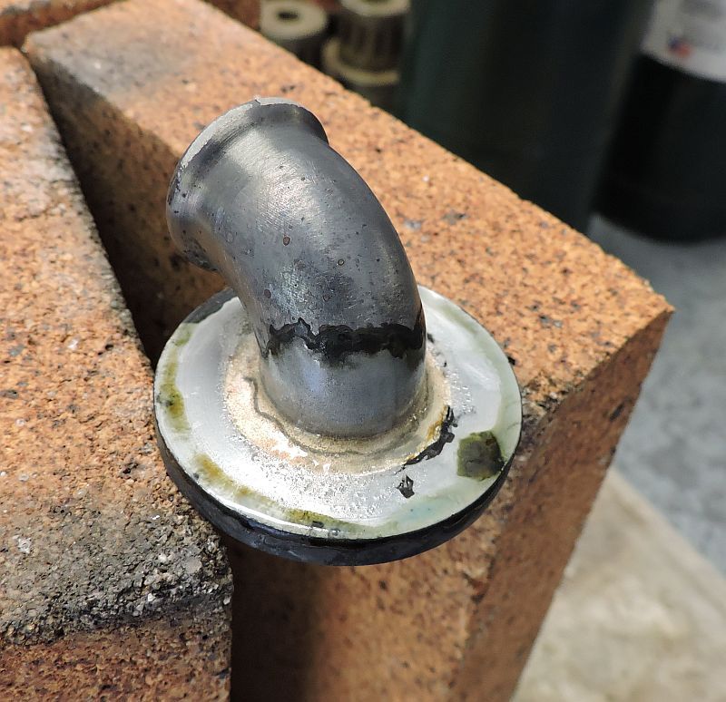
The elbow and flange are silver soldered together.
After a little clean up, the assembly is remounted to the pipe nipple and indicated in on the mill.
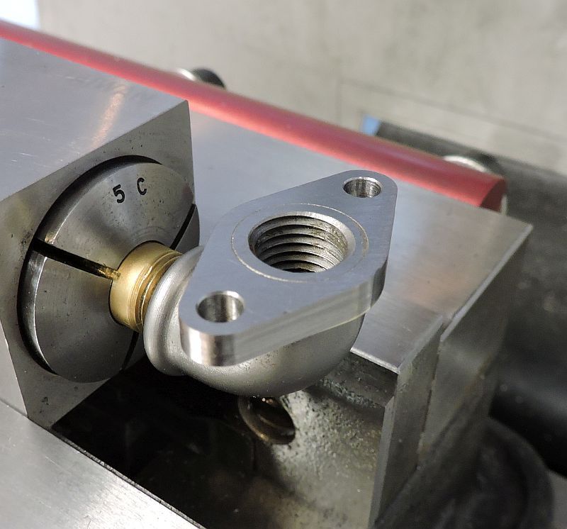
The mounting holes are drilled and the profile of the flange has been machined.
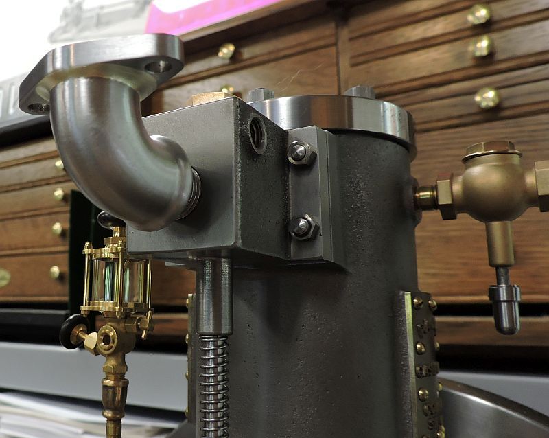
Test fitting the assembly on the engine. I probably used too much solder but it is going to be painted and I wanted a nice fillet.
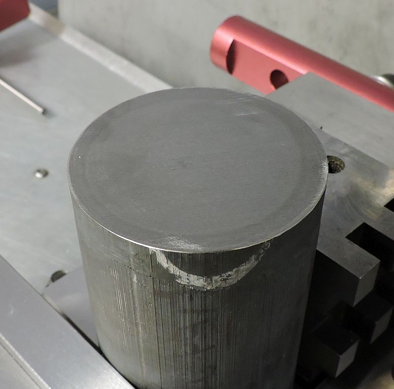
The muffler bottom started out with a 3 piece of cast iron bar stock. Thats what I had on hand and didnt want to wait for something smaller to be shipped in.
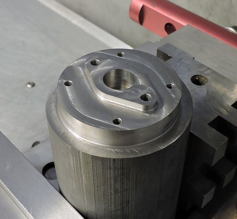
The first operation in the mill included profiling and adding the holes.
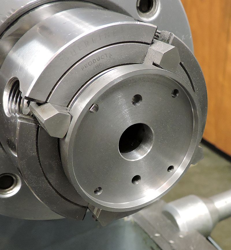
The piece was removed from the stock in the band saw, then placed in my Sherline 4 jaw chuck. It just worked out that the jaws of this chuck cleared the raised feature on the back.
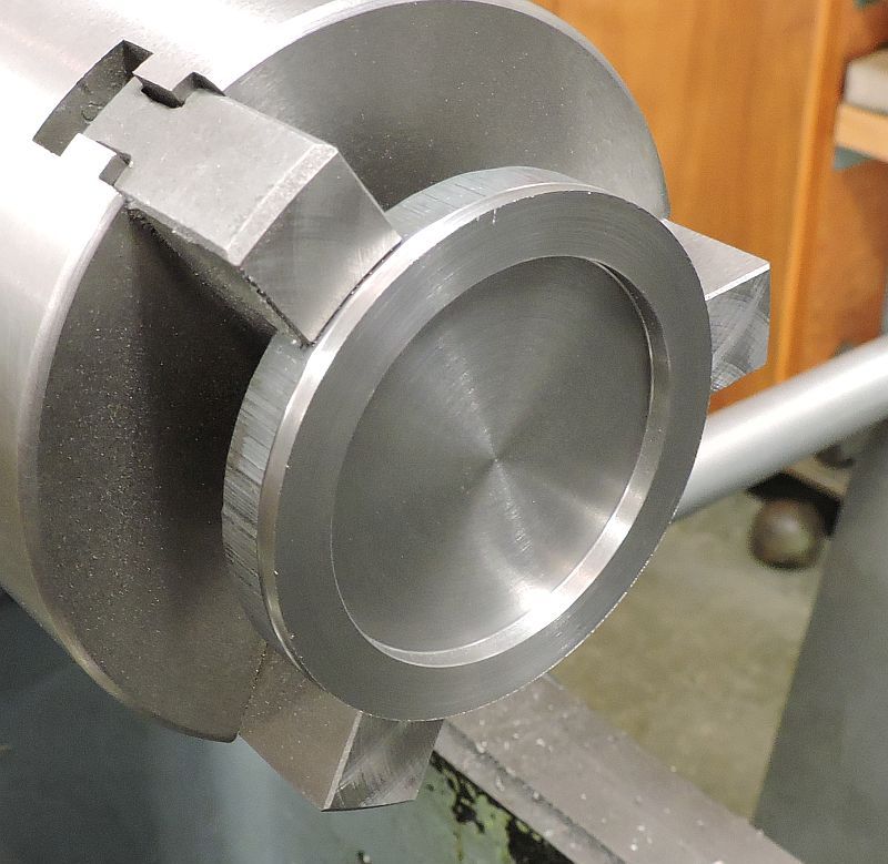
The muffler bottom was faced to length and the recess added.
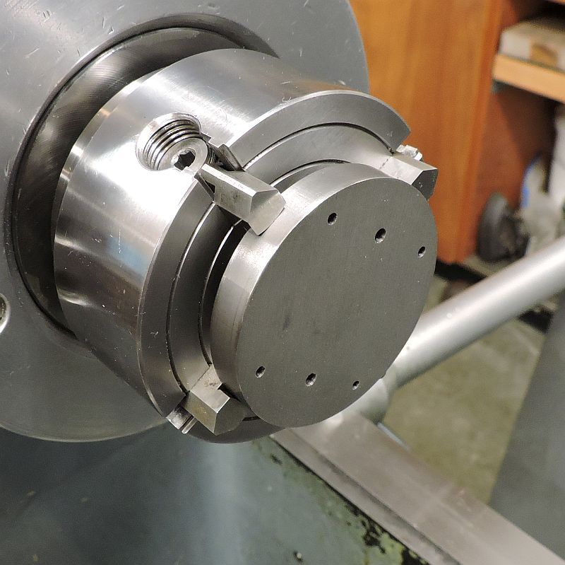
The muffler top was made using a slice of the same 3 cast iron material. The top was faced and the recess added.
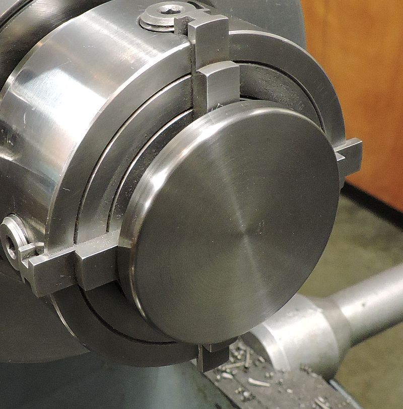
Then it was flipped around, turned to the finish diameter, and faced to length. The holes were drilled after the top was finished in the lathe.
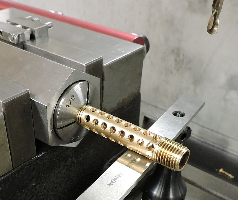
To help reduce the noise an internal baffle pipe will be included. Starting with a ¼ brass nipple; the diameter was reduced and here the holes are being drilled.
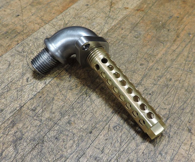
The pipe was cut to length and a plug silvered soldered in the top; then a hex was added.
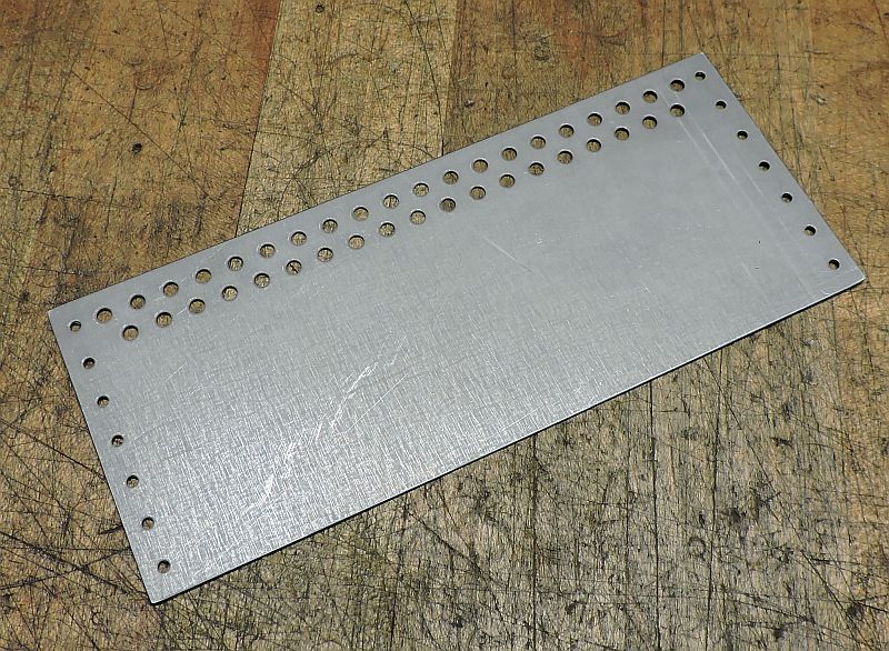
The muffler shell is rolled from .024 galvanized sheet metal. I rolled a few test pieces to determine the exact length for a flat pattern that would give me the desired 3/8 overlap; and a nice fit in the top and bottom plates. Once the length was determined a blank with the holes was punched.
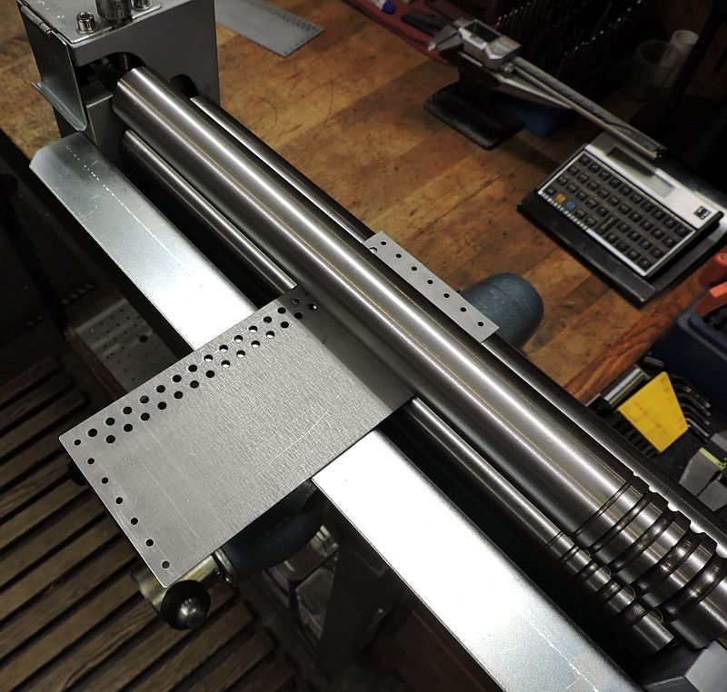
Our small slip rolls at work were too large to roll this little part so I had to purchase a new tool. I really didnt want to take the time to build my own and I didnt want to spend over a thousand dollars for a set of US made rolls; so I ordered these 1 slip rolls from Grizzly. Im quite happy with them and they work surprising well.
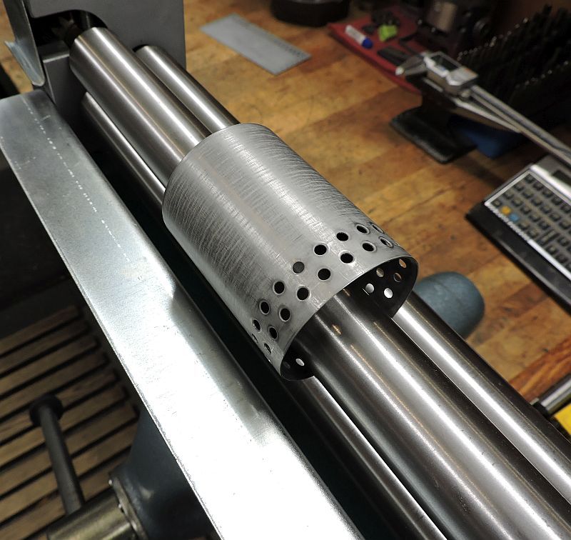
The new slip rolls made short work of rolling the muffler shell.
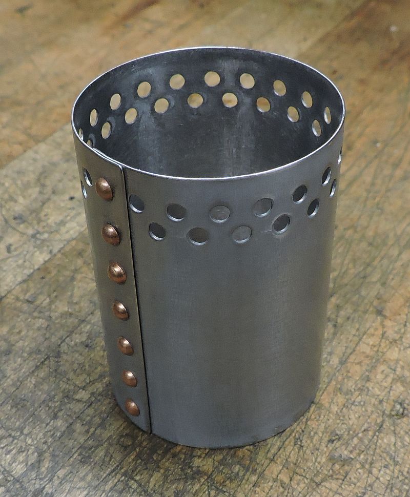
Then using some of the snaps and tooling from the water tank project; the shell was riveted together.
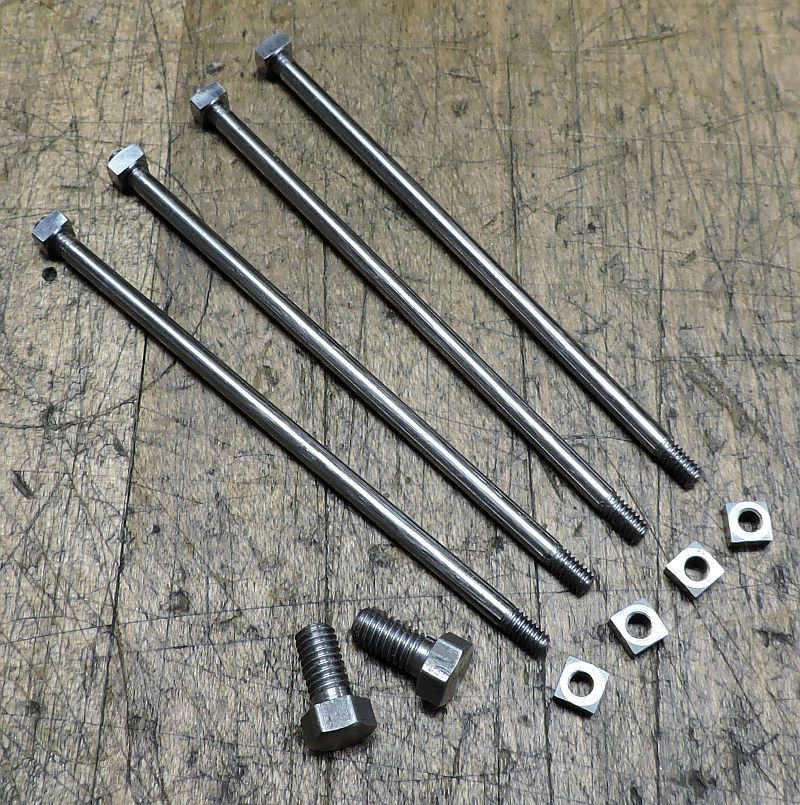
A proper set of studs and square nuts were machined.
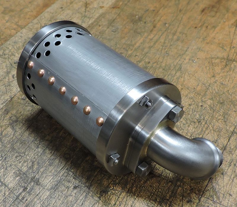
Test fit of all the pieces.
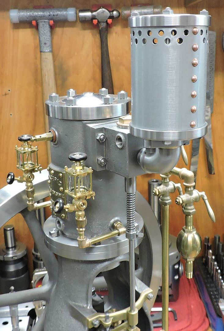
Here is a shot of the muffler installed on the engine.
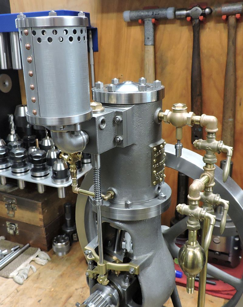
And a little different view; Im really pleased with the way it turned out.
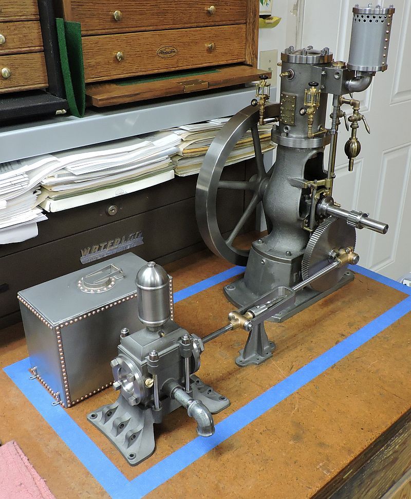
The family shot.
I have started thinking about the base to mount all the pieces on; I have some vacation coming up and hope to either get started on the display base or maybe the vapor carburetor.
Thanks for checking in.
Dave


