Author Topic: Liney RV-1 - A New Double Wide  (Read 21247 times)

Offline b.lindsey

  • Global Moderator
  • Full Member
  • *****
  • Posts: 13860
  • Dallas, NC, USA
    • Workbench-Miniatures
Re: Liney RV-1 - A New Double Wide
« Reply #60 on: November 02, 2013, 05:24:23 PM »
I think we would go with 1X if only due to the lower materials cost. There was some talk about 1.25 or 1.5X and having the students scale up the drawings on their own. Nothing finalized yet. And unfortunately I will have less of a role going forward due to my new duties and position change. Hopefully I will still have access to some of the "toys" though like the CNC machines  :)

Bill

Online Kim

  • Global Moderator
  • Full Member
  • *****
  • Posts: 7915
  • Portland, Oregon, USA
Re: Liney RV-1 - A New Double Wide
« Reply #61 on: November 02, 2013, 06:24:54 PM »
Hey Stan!  Congratulations on a runner!  She's looking good :)

And you did that in a week!?!  Wow! :o

It takes me MONTHS to do anything!  This was a blazing build!  And it runs!  What more could you ask?

Thanks for sharing it with us!
Kim

Offline sshire

  • Full Member
  • *****
  • Posts: 3044
    • LS Editions
Re: Liney RV-1 - A New Double Wide
« Reply #62 on: November 04, 2013, 05:23:04 PM »
Liney RV-1 - A New Double Wide

Part 8

Grand Finale


The speed build is done. Now to finishing and final assembly.

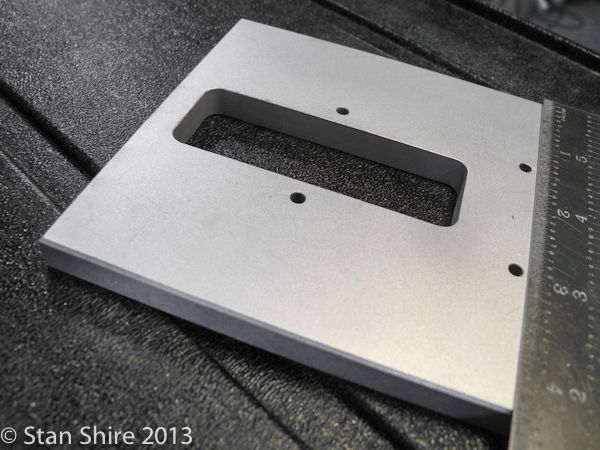
The base and flywheel will be painted. I cleaned them both with lacquer thinner. The base plate was bead blasted to give the primer something to grab.
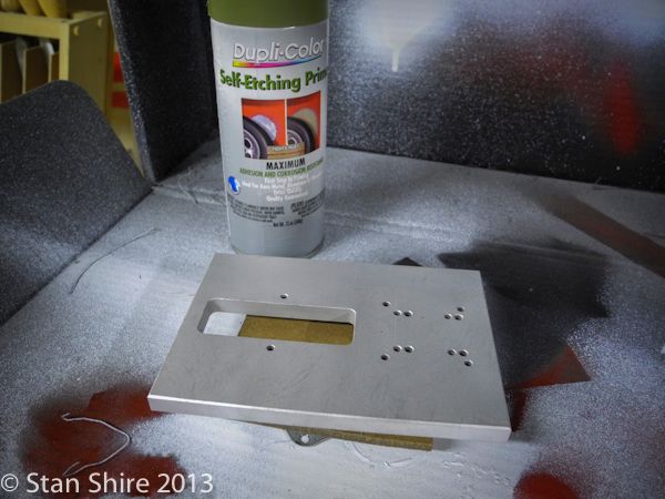


I’ve had good luck with this self-etching primer. A few light coats and it’s ready for paint.


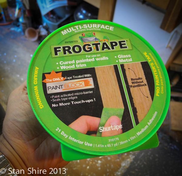
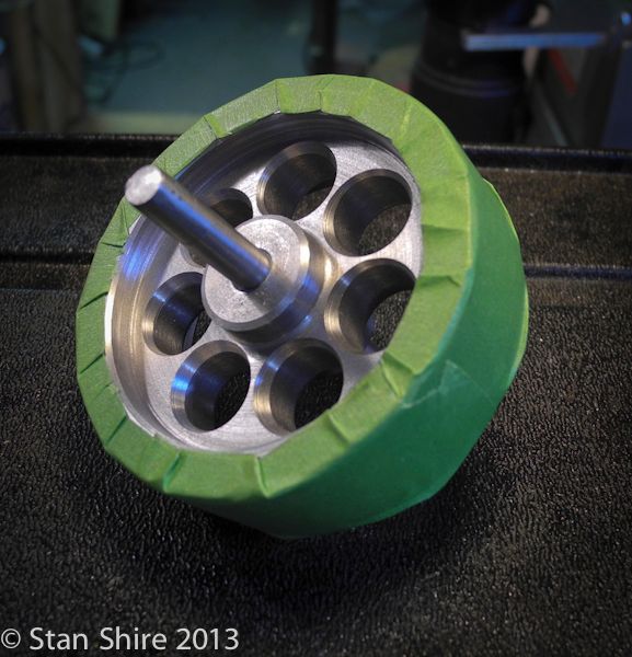
Also been happy with this masking tape. The paint does not creep under the edge. Since I had already polished the flywheel rim, I masked that.


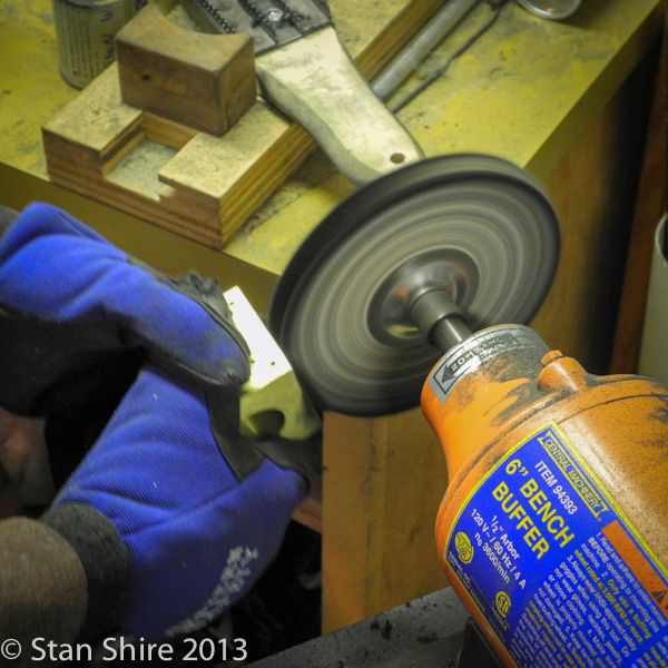
While the paint was drying, I sanded and polished the valve block.


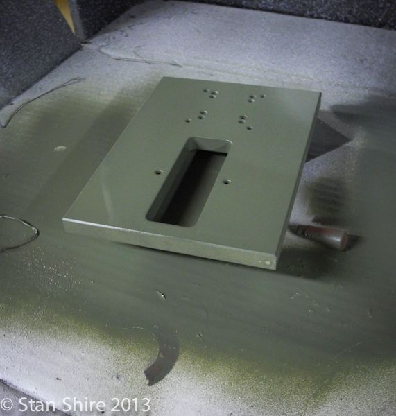
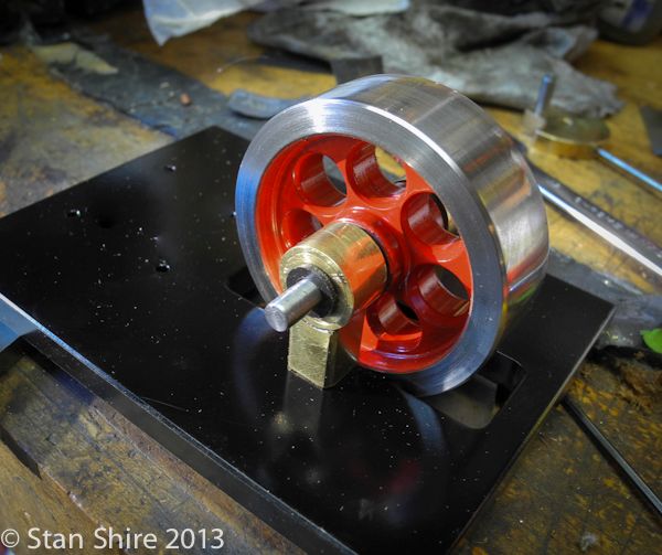
The baseplate and flywheel have three coats of paint and one coat of clear lacquer.

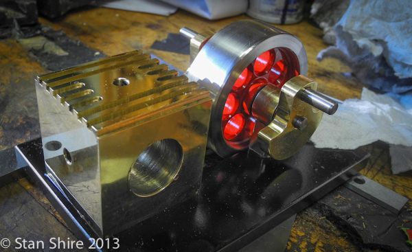
Assembly is begun with the flywheel and bearing towers.


Heading Bill’s advice about crank mis-alignment from his build, I rested both crank pins on a pair of
parallels and tightened the set screws.


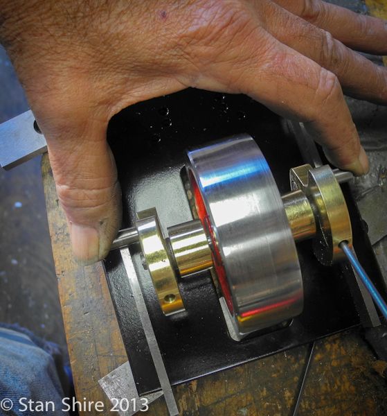
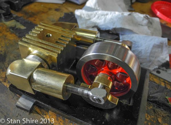
The valve block was next in line.


The rotary valve was slipped through the valve block, then one piston and cylinder was attached with a set screw. The other cylinder/piston pair was slipped on.
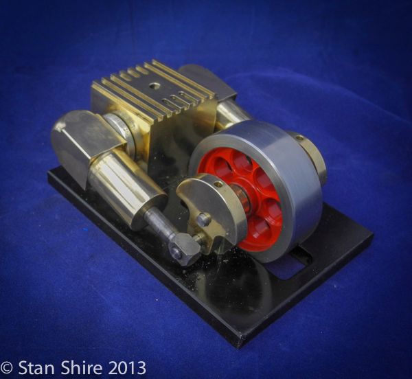


That’s it. I’ve run it for about an hour and it’s down to around 10 pounds although the compressor gauge isn’t that accurate at low pressure so it could be less or more than 10 psi.

Thanks for watching.


Video will be posted in the Finished Projects section.
Best,
Stan


SimplePortal 2.3.5 © 2008-2012, SimplePortal