That's a pretty narrow air gap at 0.02mm, but 0.2mm (0.007") is reasonable. I'm sure the radial force on the rotor increases as air gap decreases, and should balance out if everything is well centered. But a little bit of misalignment could cause unequal radial forces that would put load on the bearings and probably result in noise. Here was my original idea for pole sequence and rotation:
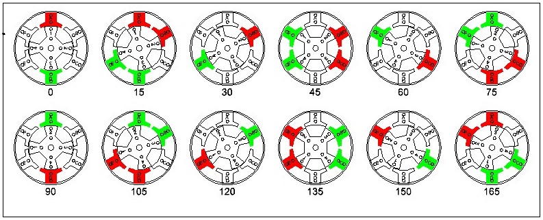
But I don't think it will work that way. Here are two other possibilities, showing the revised geometry:
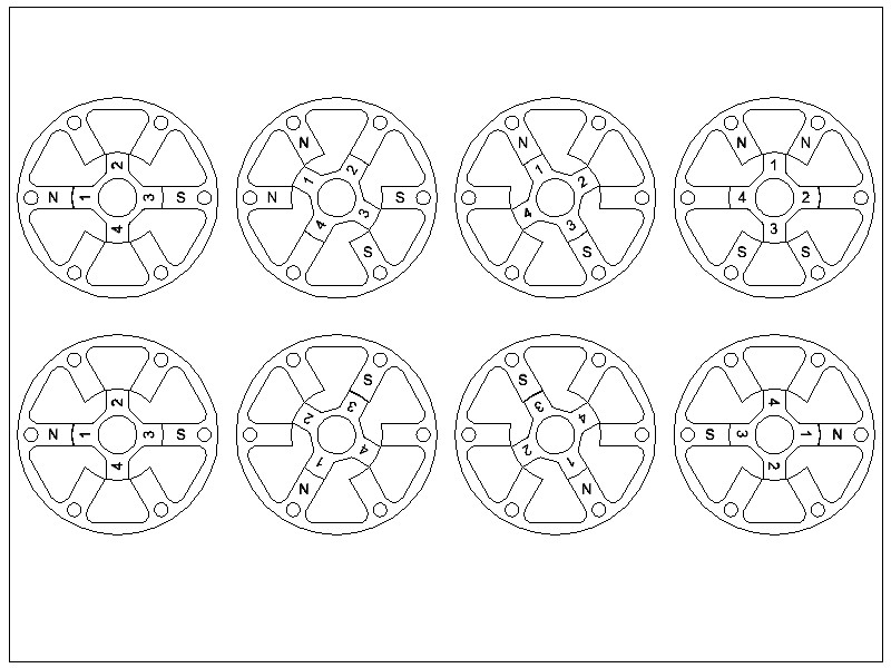
The bottom is probably the more usual sequence, but it still seems that the polarity will need to be reversed at 180 degrees. It will be interesting to experiment with this. I have a prototype board with three H-bridges that can drive each pole pair either way.
Now I am trying figure out how to do the machining. It may be difficult to hold the round washers in the mill vise, so I might drill the six mounting holes in the stator and then bolt it down to a piece of wood or scrap aluminum to drill the corner holes for milling, and there will be horizontal cuts for the left and right pole piece, and the "throat" top and bottom. Then I can rotate it 60 degrees, take more cuts, then 60 degrees again, for final cuts.
For the rotor, I may be able to do something similar, drilling small holes where the numbers are in the illustration above, and using them to bolt it to a piece of scrap. Main cuts are then horizontal and vertical. I would also need to turn it 45 degrees for the "throat" cuts.
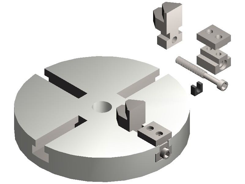
I might be able to use my rotary table, but I'd need to mount a chuck on it. I have a small chuck that fits the MT2 (or maybe MT1) center opening:
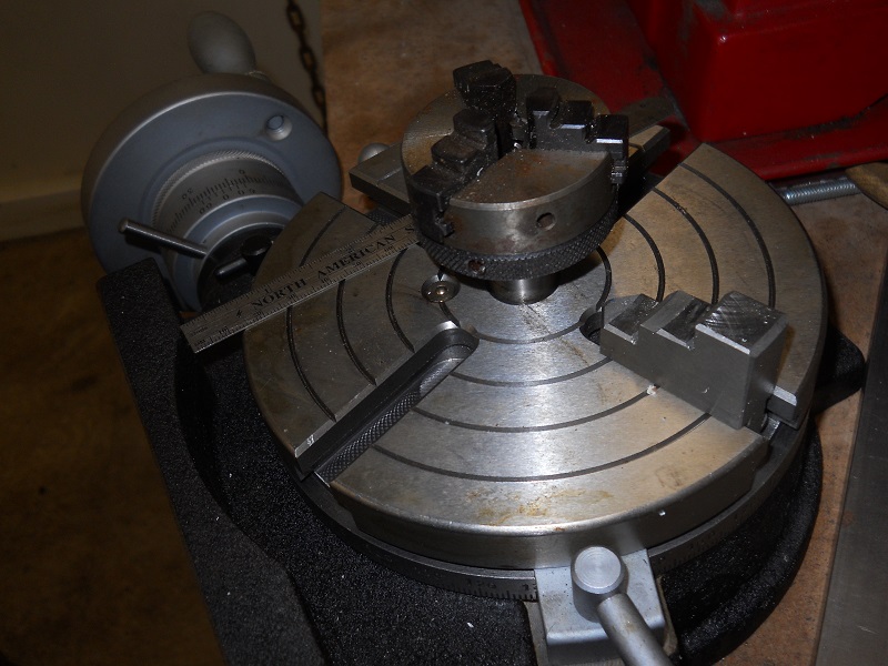
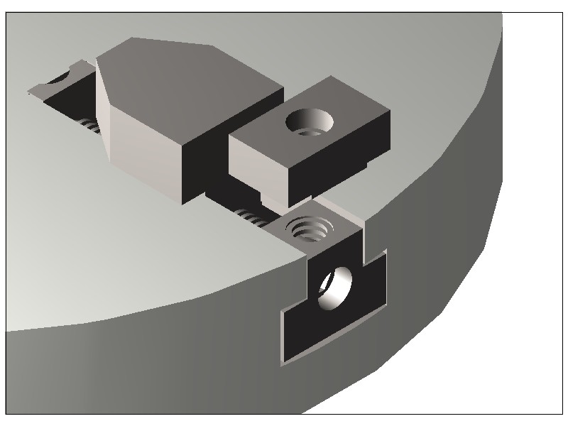
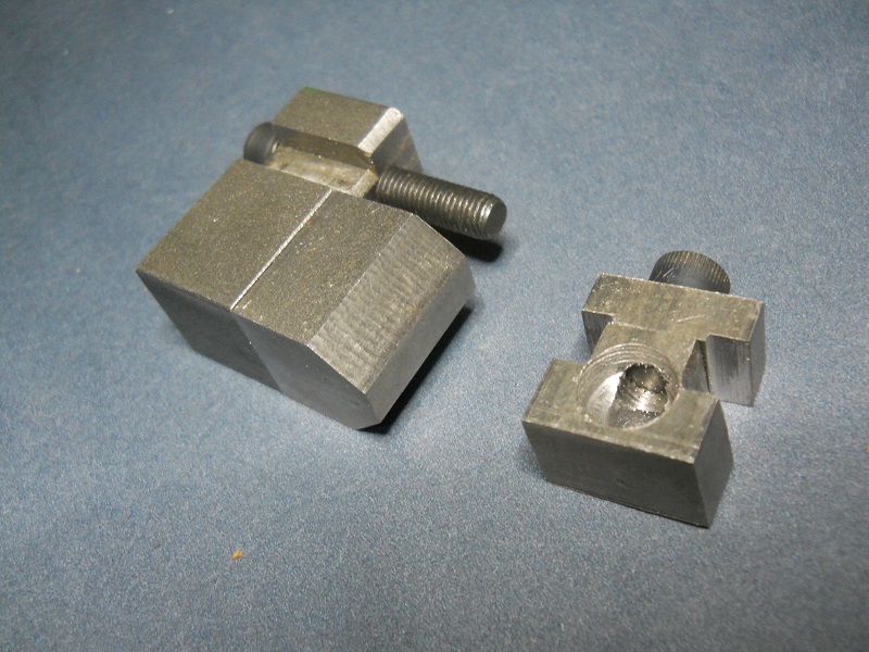
Or maybe I can finish my rotary table chuck jaw project: