Hi all,
With the Mann truck waiting for a spring thaw, its time to move on to a much smaller project that I've been wanting to build for a while - a steam powered boiler feed pump. Did a bunch of looking around at different designs/plans, and found that while they share a lot of common features, there are a lot of differences in the details of the valving. After a lot of dithering, chatting/arguing with the shop elves, and buying a variety of plans from different sources, I have settled on a version of the Weir pump based on the plans from Kennions in the UK.
The main reason for that style is that the porting/valves seems to be the simplist to make - a lot of them have a squirrels-nest of passages, all very close to each other, and look like they would be very touchy to get running. The Weir pump uses a more straightforward set of passages and valve sliders, very similar to a standard double-acting cylinder with two stacked steam chests rather than one. So, that one wins out - though I am building it double the size shown in the plans.
Making it larger should make it a bit less touchy on the timing adjustments, and hopefully will result in running slower than really small engines tend to want to. It winds up with a 3/4" diameter piston and a cylinder block 1-5/8" long, which I can get out of some chunks of brass bar sitting on the stock shelf already. It looks like I can build the entire project with material already on hand, which is handy.

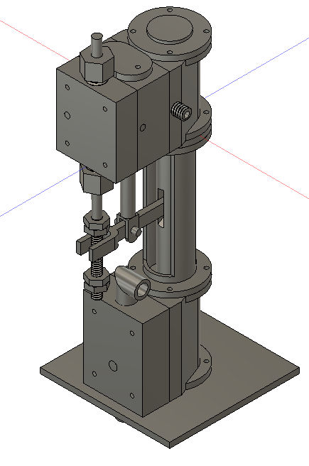
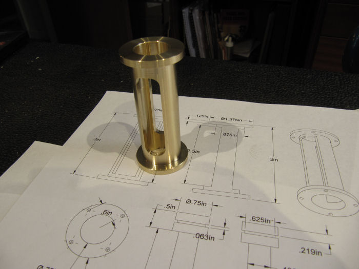
To make it easier to follow the plans without having to remember to double everything on the fly, and to adjust a few things to use the fastener sizes I like, it was first drawn up in Fusion as a 3D CAD model, and new plans at the larger size printed out. Here is what it should end up looking like:
Construction started the other day, so I'll get caught up - all this was NOT done in a day!
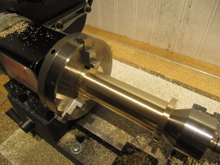
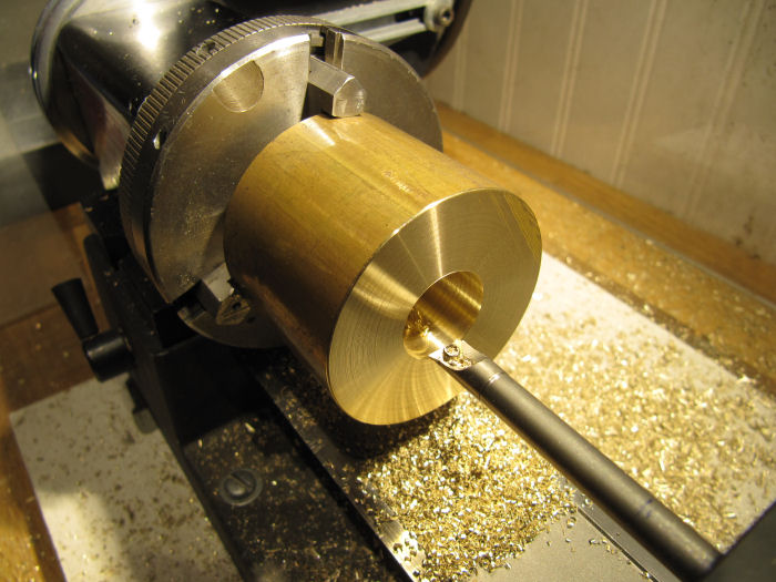
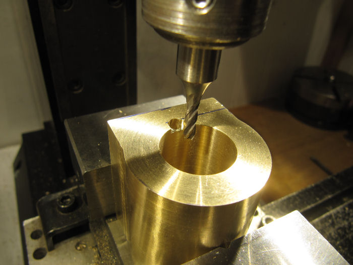
Started with the center seperator, which looks like a crosshead guide, but it is just a spacer - nothing will be touching the inside of the tube. Drilled/bored the center opening, then turned the outside to shape.
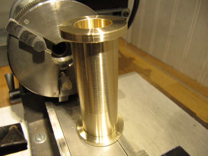
Then bored out the openings in the sides - these give room for the reversing arm to go from the piston rod out to the valve rod.
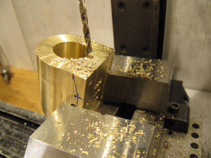
The next day, I started in on the cylinder block (actually am doing the same outside shaping on the bottom valve block as well, they are the same outside shape but with different bores). First drilled/bored out the cylinder:
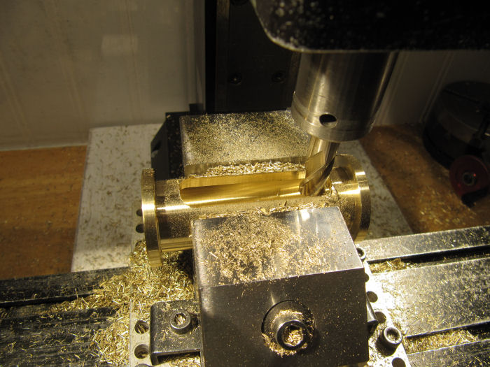
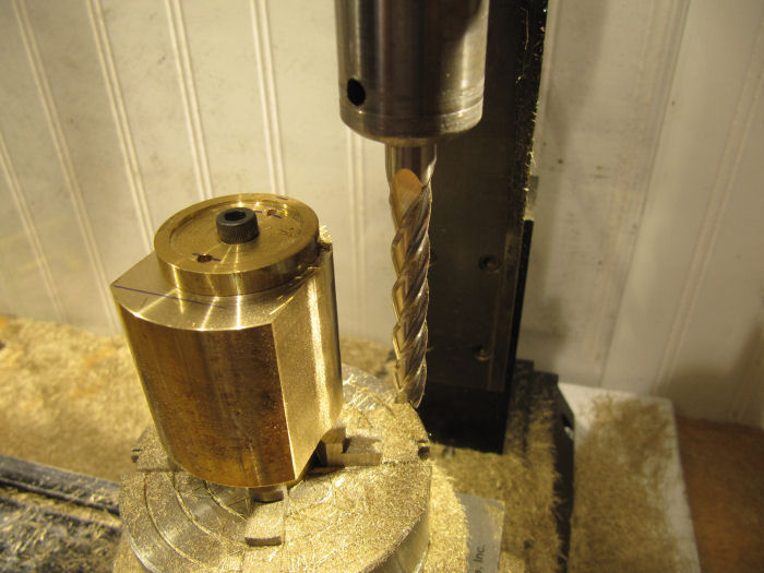
Then set it up on an arbor on the mill, also known as the Swarf Maker, to round the three sides behind the steam chest base:
and flattened off the port face of the steam chest base.
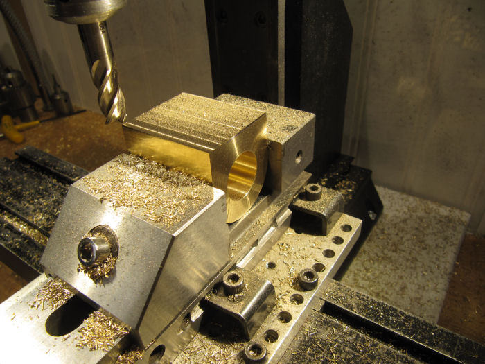
While the block was still leveled up in the vise, went ahead and milled in the steam ports, identical to a standard double acting cylinder:
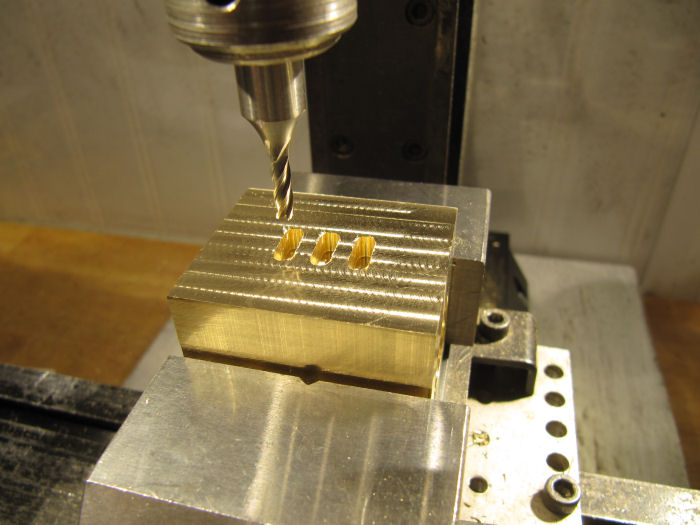
plus the mounting holes and the hole for the passage into the valve chests above - here is where it starts varying from a standard engine, this passage will feed steam up to the reversing valve.
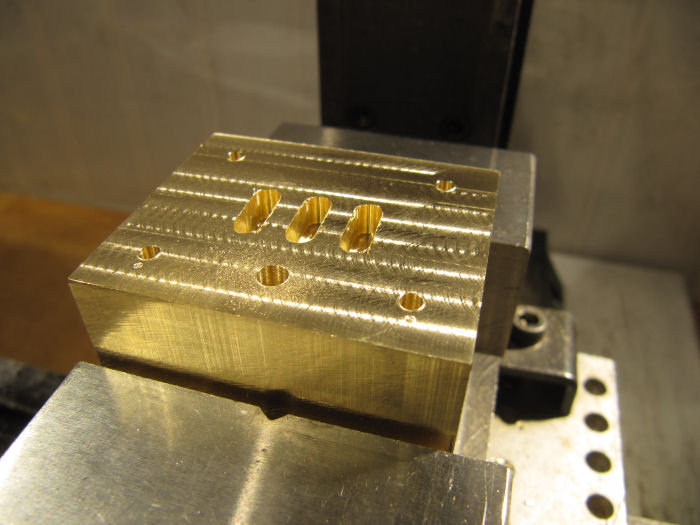
Also drilled the passages from the cylinder ends to the outer valve ports, first milling a flat so the drill would not skate:
finished up by milling the openings from those holes to the ends of the cylinder:
Thats where it sits at the moment - next stage will be to set up the rotary table vertically to mill the open spaces between the end flanges on the cylinder blocks. Its all going pretty quickly, love how easily brass machines!
Chris


